The Project Gutenberg EBook of Making Tin Can Toys, by Edward Thatcher

This eBook is for the use of anyone anywhere at no cost and with
almost no restrictions whatsoever.  You may copy it, give it away or
re-use it under the terms of the Project Gutenberg License included
with this eBook or online at www.gutenberg.org/license


Title: Making Tin Can Toys

Author: Edward Thatcher

Illustrator: Isabel Thatcher

Release Date: April 7, 2018 [EBook #56939]

Language: English

Character set encoding: UTF-8

*** START OF THIS PROJECT GUTENBERG EBOOK MAKING TIN CAN TOYS ***


Produced by Chris Curnow and the Online Distributed
Proofreading Team at http://www.pgdp.net (This file was
produced from images generously made available by The
Internet Archive)
MAKING TIN CAN TOYS
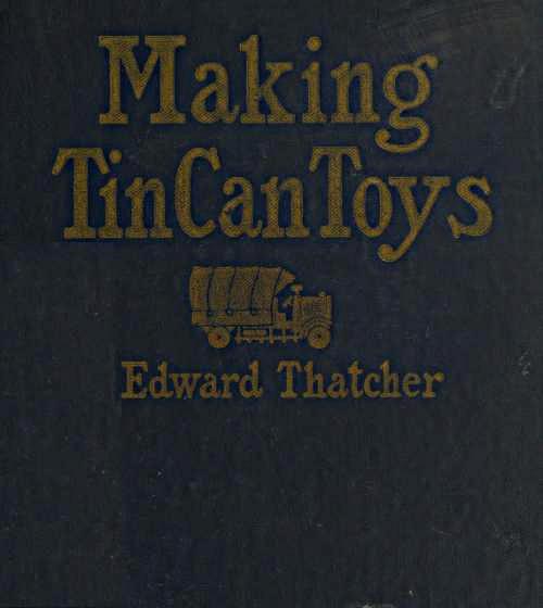
Army truck constructed entirely from used tin cans
MAKING TIN CAN TOYS
BY
EDWARD THATCHER
ORIGINATOR OF TIN CAN TOYS AND INSTRUCTOR OF METAL
WORKING, TEACHERS COLLEGE, COLUMBIA UNIVERSITY
NEW YORK CITY, 1904-1919
DRAWINGS MADE AND THE
AUTHOR’S MODELS PAINTED
By ISABEL THATCHER

PHILADELPHIA AND LONDON
J. B. LIPPINCOTT COMPANY
COPYRIGHT, 1919, BY J. B. LIPPINCOTT COMPANY
PRINTED BY J. B. LIPPINCOTT COMPANY
AT THE WASHINGTON SQUARE PRESS
PHILADELPHIA, U. S. A.
Tin can toys were invented after a fruitless search of the toy shops for a large tin locomotive. I had a long can in my shop at home that I thought could be very easily worked up into a toy locomotive boiler by adding a few fittings, such as a piece of tin rolled up into the form of a smokestack. Part of a small can could be used for a steam dome, or I could use the top part of a certain tooth-powder can, the distributor top of which would look very much like a whistle. A cocoa tin came in very handy for a cab, and a thumb-tack box served for a headlight. The wheels were made of can lids soldered together, and the toy locomotive was made, much to the joy of my very young son, who has had it in constant service for over a year, and it is still good for many trips at the end of a string.
I had always used tin cans for making such articles as water motors, glue pots, melting ladles, mooring buoys for model yachts, etc., but the locomotive was the first toy, made wholly from tin cans, that I had produced, and this suggested other toys. The steam roller was next made.
I found that the cans lend themselves very easily[2] to the making of toys, so much of the work being already done.
The materials used to make these toys are plentiful and inexpensive—cans are everywhere. The tools needed are few and easy to use, and I found that so many different and amusing durable toys could be made from used tin cans, and also that everyone seemed to have such fun making the toys, that I decided to use them for teaching purposes.
Tin can toy making has been thoroughly tried out in a grade school under a very able teacher, who understands making them. Pupils of ten, eleven and twelve years of age have proved that these toys are easy to make, and many schools now have the work well established.
The steam roller, shown in Plate XI, was made by a boy of ten after a model which I made for it. This same boy developed quite a trade of his own by soldering up various pieces of tinware for his mother and the neighbors.
But, better still, working with the tin cans has developed the inventive faculties of my class to a surprising degree. The pupils have thought out and made many models of their own—not only toys but useful things as well. Various members of the class investigated the large trucks, automobiles, hoisting engines, locomotives, boats and such things seen in[3] any water-front community, to see how they were made and how they worked, and why. These pupils then returned to the school shops and made models of their own, many of which showed considerable invention and ingenuity.
I decided to teach the Occupational Aides in my classes at Columbia University how to make these toys, so that they in turn could teach the wounded soldiers in the hospitals.
It is a great pleasure to know that as this book goes to press many a wounded soldier has been and is still being amused and benefited by making the tin can toys here.
But the making of tin can toys is by no means limited to hospitals and schools. Any one who cares to tinker, to handle tools, to use up waste materials, may find pleasure and profit from assembling tin cans and parts of them. Many useful and attractive things may be made for the home, shop, or camp.
I have found it quite possible to make many decorative things from tin cans, and for some years I have made lanterns, candlesticks, sconces and trays of all kinds. The shape of the cans themselves lends them to decoration when assembled by a person having a sense of design and proportion.
There is nothing weak or flimsy about a well-made tin can toy. A strip of flat tin is very easily[4] bent; if that same strip of tin is bent at right angles through its whole length, like the angle iron encountered in structural iron work, it will be found to be remarkably stiff.
Bend up an angle on each side of a strip of tin, like a channel iron used in buildings; it will sustain a remarkable load.
I have used the common forms employed in structural steel for building up the toys shown in this book with the result that they are surprisingly solid and durable, though made entirely from cans or the tin taken from flattened-out cans and boxes.
No rough or sharp edges are left about these toys. The edges of a piece of tin may be folded over or “hemmed”—or a folded strip of tin may be slipped over an edge that needs strengthening. Thus all danger of cutting the fingers or of thin edges being bent out of shape is done away with.
Although made of tin, there need be nothing “tinny” about a well-made, well-painted tin can toy.
Very few and very simple tools are required for the work and the solder, soldering flux, rivets, wire and paint are very inexpensive items, as so little need be used for each piece produced.
Soldering is by far the most important of the operations involved in tin can toy making. But it is very simple, once it is understood. When the[5] principles that govern the process of soldering are thoroughly mastered there is no difficulty at all about it. Chapters IV and V should be thoroughly read and re-read before trying to solder, and at least two practice pieces well soldered together before going any further.
Since the tin can toys were introduced into my classes at college I have taught more than two hundred pupils how to make them. Many of these pupils had little or no experience with tools and had never expected to have any until the war came along and changed the ideas of many people as to their ability to work with their hands. I have yet to encounter a pupil who could not solder after a very short period of instruction.
Look at the end of a small olive oil can or the end of a tin commonly used to contain cocoa, then think of the shape of the radiator and hood of the modern automobile. The shape of the can and the shape of the hood of the automobile are very much alike. A few holes punched in the end of the can in regular rows transform it into a miniature radiator in appearance, and some slits cut in the side of the can look very much like the vents in the side of a real auto hood. Solder the cap of a tooth-paste or paint tube in place over the radiator, and the hood and radiator are completed.
To have formed up a hood of this sort from a plain sheet of metal would have taken far more skill than the average tinker is likely to possess, but you have it ready made in the can, and this is the whole idea of tin can toy building.
Less than half of a rectangular two-quart can used for a certain cooking oil makes up into a truck body so like the bodies on the real trucks that it would be difficult to find or make one more like them.
Many different kinds of boats that will really float may be made from mackerel and herring tins which are usually made in the shape of boats. Two mackerel tins soldered together suggest the fighting tank. Only a little work is necessary to transform these cans into real toys.
Long cylindrical cans suggest boilers for toy locomotives, hoisting and traction engines, steam rollers and the like.
Wheels for rolling stock may be made from cans or the can lids. Small adhesive tape boxes make excellent headlights or searchlights and also pilot houses for tiny tug boats. Bottle caps, thumb-tack boxes, and the small screw tops of olive or cooking oil cans suggest head, side and tail lights for toy automobiles, and many other things.
Aside from the pleasure derived from the actual making of tin can toys, perhaps the greatest[7] satisfaction lies in the fact that you are using material usually thrown away—making something out of nothing.
And so this book is offered to tinkers by a tinker with the hope that they may get some of the pleasure out of it that he has had in writing it.
Edward Thatcher.
Woodstock, Ulster County, New York.
September, 1919.
RECONSTRUCTION AIDE, DIRECTOR OF THE RED CROSS WORK SHOP FOR PATIENTS AT NEUROLOGICAL BASE HOSPITAL 117, LA FAUCHE, HAUTE MARNE, FRANCE
“The hospital was new and its needs were many. We began work the day after our arrival and by the time our small equipment was unpacked (Mrs. Myers refers here to her own personal equipment of tools which was necessarily a small one as it was brought from America. The hospital shops were not equipped with tools until after the Aides had established the work and decided on the necessary tools needed), requests were coming in from all quarters of the hospital for us to make everything from tables and dishes to doughnut cutters. There was such a lack of material that the problem of making them could have been solved by nothing less than ingenuity of the American soldier and the ever present tin can pile.
“Some old French hospital beds found on the salvage heap were quickly converted into work benches. It was then that the tin can ceased to be a thing to be burned and buried and came into its own.
“Our first need was a charcoal furnace to heat[10] our soldering coppers. This was made from two large square tins with an interlining of brick. A bit of an old grate completed this perfectly good furnace which served us well for many months.
“The wants of the kitchen were next considered. For washing dishes we made three huge wooden tubs 2 by 2½ by 6 feet. The lining and drain pipes for these were made from several large tin cans. As the size of the hospital increased there was a constant demand for such things as biscuit pans, doughnut cutters, funnels, potato graters, vegetable strainers, soap dishes and other small necessities.
“For the officers’ wards, barracks, and recreation hut, we made tin candlesticks, flower holders, ash trays, electric light shades, tea trays, desk sets, and filing boxes. All of which were not only useful but quite ornamental, as they were attractively painted and decorated by the patients. The soldiers took great interest in the making of mechanical toys, especially war-like ones, such as tanks, aeroplanes, cannon and army trucks.
“The reflectors for the foot lights of the stage in the Red Cross Recreation Hut were made of tin cans. The end-men in the minstrel show were quite gay in tin can hats—what could have been more simple—a tin brim with an inverted butter can for a crown, gaudily painted and beribboned!
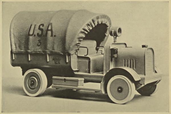
PLATE I
Courtesy Pictorial Review
Wounded soldiers at work
“The princess in the Christmas play was in need of shining armor. Half circles of tin overlapping[11] each other not only served the purpose but were glitteringly gorgeous. The Three Kings in the play were badly in need of crowns; three oatmeal tins were beautifully fashioned into kingly headdresses for them.
“The Christmas tree was brilliant with hundreds of stars, diamonds, and crescents, and candle holders, which was the final contribution of our much sought and never failing friend, the tin can pile, as the hospital was evacuated soon afterwards.
“I have had entire charge of the work and have taught the other Aides the tin can work, as it was a most necessary thing for them to know. Many of these Aides were sent to other hospital workshops and introduced the work there.”
Mrs. Clyde M. Myers, R.A.
| CHAPTER | PAGE | |
| Introduction | 5 | |
| Extract from a Letter Written from France by Mrs. Clyde M. Myers, R.A. | 13 | |
| I. | Tin Cans | 19 |
| VARIOUS KINDS OF CANS AND BOXES—PREPARING CANS FOR THE WORK—CUTTING IN AND OPENING OUT CANS AND BOXES | ||
| II. | Tools and Appliances | 28 |
| TOOL LISTS AND COSTS—LAYING OUT AND MARKING OFF WORK—SHOP APPLIANCES | ||
| III. | Making a Biscuit Cutter from a Small Can | 44 |
| CUTTING THE CAN TO SIZE FOR BISCUIT CUTTER—PUNCHING A HOLE IN TIN—FORMING THE HANDLE—FOLDING—MAKING A SUGAR SCOOP BY THE SAME METHOD | ||
| IV. | Soldering | 54 |
| SOFT SOLDER—SHEET TIN—THE PROCESS OF SOLDERING—HEATING APPARATUS—ELECTRICAL SOLDERING COPPERS—THE COMMON SOLDERING COPPER—FLUXES—TINNING THE COPPER—HEATING | ||
| V. | Soldering (Continued) | 71 |
| PREPARING A JOINT FOR SOLDERING—CLEANING AND SCRAPING—SOLDERING A PRACTICE PIECE—SOLDERING THE HANDLE TO THE BISCUIT CUTTER—A SECOND PRACTICE PIECE—ANOTHER METHOD OF APPLYING SOLDER | ||
| VI. | Cooky Cutters | 79 |
| THE PINE TREE DESIGN—CUTTING NARROW STRIPS OF TIN—BENDING TO SHAPE OVER DESIGN—SOLDERING COOKY CUTTERS—THE HANDLE | ||
| VII. | Trays | 86 |
| TURNING OVER EDGES ON ROUND TRAYS—USING THE FORMING MALLET—MAKING AN ASH TRAY AND MATCH BOX HOLDER[14] | ||
| VIII. | A Tray Candlestick | 94 |
| THE CANDLE SOCKET—CUTTING A HOLE IN THE DRIP CUP—MAKING THE HANDLE | ||
| IX. | Riveting | 100 |
| MAKING A PAIL FROM A TIN CAN—CUTTING AWAY THE SURPLUS TIN AT THE RIM—FORMING THE LUGS FOR THE HANDLE—RIVETING THE LUGS IN POSITION—FORMING A WIRE HANDLE | ||
| X. | Making a Toy Auto Truck | 107 |
| FOUR WAYS OF MAKING WHEELS OF TIN CANS: MAKING A WHEEL FROM A CAN WITH SOLDERED ENDS—MAKING WHEELS FROM ROLLED RIM CANS—TWO TYPES OF WHEELS MADE FROM CAN LIDS | ||
| XI. | Making a Toy Auto Truck (Continued) | 118 |
| FORMING THE CHASSIS—USING THE WOODEN ROOFING FOLDER—FOLDING—USING THE VISE FOR SHORT FOLDING—USING THE HATCHET STAKE FOR FOLDING | ||
| XII. | Making a Toy Auto Truck (Continued) | 127 |
| MAKING THE HOOD AND RADIATOR—CUTTING THE VENTS—SOLDERING ON THE FILLER CAP | ||
| XIII. | Making a Toy Auto Truck (Continued) | 135 |
| THE DASH-BOARD—THE SEAT—ASSEMBLING THE TRUCK—SPRINGS—SOLDERING THE WHEELS ON THE AXLES—STRIP WASHERS | ||
| XIV. | Making a Toy Auto Truck (Continued) | 146 |
| TRUCK BODIES—DIFFERENT TYPES OF BODIES TO BE FITTED TO THE SAME CHASSIS—THE TANK TRUCK—THE STREET SPRINKLER—THE COAL OR SAND TRUCK—THE ARMY TRUCK—THE AMBULANCE—THE FIRE ENGINE | ||
| XV. | Making a Toy Auto Truck (Continued) | 157 |
| THE STARTING CRANK—THE STEERING WHEEL AND COLUMN—MUD GUARDS AND RUNNING BOARDS—LIGHTS, TOOL BOXES, HORNS, ETC.,—DRIVERS’ CABS | ||
| XVI. | Boats | 166 |
| THE ROWBOAT—THE SAILBOAT—THE SCOW—THE TUGBOAT—THE BATTLESHIP—THE FERRY-BOAT[15] | ||
| XVII. | A Toy Locomotive | 174 |
| THE FRAME—BOILER—CAB—WHEELS—CYLINDERS AND CONNECTING RODS—THE SMOKESTACK, STEAM DOME AND WHISTLE, SAND BOX AND HEADLIGHT—CARS—A PASSENGER CAR AND SOME OTHERS | ||
| XVIII. | Simple mechanical Toys | 182 |
| WATER WHEELS AND SANDMILLS—A SIMPLE STEAM TURBINE AND BOILER—A WINDMILL AND TOWER—AEROPLANE WEATHERVANE | ||
| XIX. | Candlesticks | 192 |
| WALL SCONCES AND A LANTERN | ||
| XX. | Camp and Kitchen Equipment | 195 |
| A COFFEE POT—BOILING PAILS—FRYING PAN—TOASTER—A CAMP SHOWER BATH—CANTEEN OR HOT WATER BOTTLE—A MATCH BOX | ||
| XXI. | Preparing the Toys for Painting | 200 |
| REMOVING SURPLUS SOLDER WITH SCRAPERS—MAKING A HOE SCRAPER—PLUMBERS’ AND ROOFERS’ SCRAPERS—SCRAPING AND FILING—BOILING THE TOYS IN A LYE BATH—VENT HOLES | ||
| XXII. | Notes on Painting the Toys | 206 |
| PAGE | ||
| Army Truck Constructed Entirely from Used Tin Cans | Frontispiece | |
| I. | Wounded Soldiers at Work | 10 |
| II. | Army Truck and Tin Cans Used to Make It | 22 |
| III. | The Raw Material from Which Many of the Toys Shown in This Book Were Made | 23 |
| IV. | Scribing a Line Around a Can with the Dividers. Cutting Along the Joint to Open a Can. Cutting from Right to Left with the Straight Shears. Cutting to the Line, Right to Left | 22 |
| V. | Author at Work | 23 |
| VI. | The Tools Needed for Tin Can Toy Making | 32 |
| VII. | Biscuit Cutters. Soldering | 44 |
| VIII. | Cooky Cutter, Tray Candlestick and Ash Trays Made by the Author | 84 |
| IX. | Steam Rollers | 116 |
| X. | Dumping Truck and Chassis of Toy Auto Truck. | 120 |
| XI. | Chassis of Toy Auto Truck and Dumping Truck. | 121 |
| XII. | Wooden Roofing Folder | 120 |
| XIII. | Oil Tank Truck and Toy Ford | 152 |
| XIV. | Red Cross Ambulance | 153 |
| XV. | Boats | 170 |
| XVI. | A Simple Toy Locomotive, a Sand or Water Mill and the First Tin Can Toy | 174 |
| XVII. | Steam Tractor and Gun | 175 |
| XVIII. | Aeroplane Weathervanes | 188 |
| XIX. | Lantern and Fighting Tank | 192 |
| XX. | A Toy Tin Can Kitchen | 196 |
| XXI. | A Doll’s Bathroom and a Tin Can Laundry | 197 |
VARIOUS KINDS OF CANS AND BOXES—PREPARING CANS FOR THE WORK—CUTTING IN AND OPENING OUT CANS AND BOXES
There are many shapes and sizes of tin cans and boxes as every one knows; round, square, elliptical, tall, short, or flat. A surprising number of attractive shapes and sizes may be collected in a short time in any community. Housewives are only too glad to find some one to use them.
Cans that are well rinsed with hot water as soon as the contents are removed are not at all objectionable to work with; but cans that have not been rinsed out, or that have been thrown out and exposed to the weather are very unpleasant objects, and besides, a rusty can is very difficult to solder. It is a simple matter to rinse or scald out a can as soon as the contents are removed.
Tomato, corn, pea and condensed milk cans are the most plentiful. Coffee, tea, cocoa, jam, mackerel and sardine cans, olive and cooking oil cans, baking powder and spice cans are all useful for making the[20] things described in this book and for many more besides. Biscuit boxes, tobacco boxes, cold cream, ointment, and the small adhesive tape boxes all contain possibilities. The screw tops of olive oil and cooking oil cans, and bottle caps should be collected for this work. Jelly glass lids, in fact, all shallow tin lids are useful. Syrup and molasses cans with separate lids, that push into place are worth saving, especially the lids. Certain containers of dry material are now largely made of pasteboard with tin tops, lids and bottoms. The tin parts of these containers are often of an attractive shape. The large round gallon cans used by hotels and restaurants are particularly useful, and a sizable piece of tin may be obtained from the sides of the can and the bottoms may be used for large candlestick saucers and many other things. Large square tin boxes used to contain 100 pounds of cocoa may be obtained from some restaurants. These are made of heavy tin and five large sheets may be cut from the bottom and sides. Considerably over $1 would have to be paid for the same amount of tin.
Preparing Cans for the Work.—Cans that have contained paint, stove-blacking, heavy oils or greases, or cans that have been standing about with part of the contents exposed to the air may be thoroughly cleaned of all foreign matter by the hot lye bath. This bath is made up by adding two heaping tablespoonfuls of lye or washing soda to the gallon[21] of boiling water. Cans boiled up in this solution for a few minutes will be cleaned of all paint, paper labels, etc. Keep the hands out of the solution and do not allow any of it to come in contact with the clothes. Lift the work out of it with a wire hook and rinse off the lye with hot water; stand the cans bottom up so that they will drain out without any water remaining in them. The lye solution may be used for a number of times and then may be poured down the sink, as lye is an excellent thing for drain pipes. Do not leave a lye bath in the shop without covering it tightly when not in use, as the fumes from it are sure to rust every tool in the place.
Coffee, tea, cocoa, talcum and other cans that have contained dry material need not be put in the lye bath until ready to paint, unless the labels are too much in the way for soldering. Small boxes such as contain tobacco are almost covered with a sort of varnished paint. This may be scraped away where the box is to be soldered, but if much soldering is to be done the whole box should be boiled up in the lye bath until all the paint is removed. Sometimes the lye softens the paint but does not entirely remove it. More lye may be added to the bath and the work left in it awhile longer, or the work may be removed from the bath and the softened paint scrubbed away with a scrubbing brush and plenty of clean water. After being used several times, the bath will become too muddy and weak for further[22] use and then a fresh one should be made, as the lye is inexpensive.
For good work, it is necessary that the cans be thoroughly clean.
Cutting Into and Opening Out Cans and Boxes.—There is one very easy way to cut into and open out a can or box. To make wheels, small trays and other things, a good part of the sides of the can must be cut away leaving a small portion of the sides attached to the bottom. The part that is cut away may be flattened out and used to make various things. As most of the cans used are cut down to various dimensions in this manner, either to use the bottom with part of the sides, or to obtain flat sheets of tin, it will be well to consider the easiest way of doing it.
First, determine how much of the bottom portion of the can is to be left intact. Then using a pair of dividers opened to this dimension, make a line parallel with the base of the can and completely around it. To do this, hold the can down to the bench with the left hand so that it may be turned against the divider points as shown in Plate IV, a. Hold the dividers firmly down to the bench and against the can so that the uppermost point is held at exactly the same height from the bench during the turning or marking, while turning the can against the point to mark it.
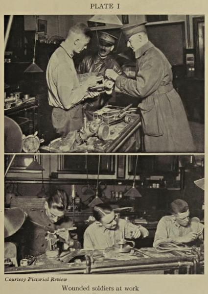
PLATE II
Army truck shown in frontispiece assembled from group of cans shown below
Tin cans used to make the army truck shown in frontispiece
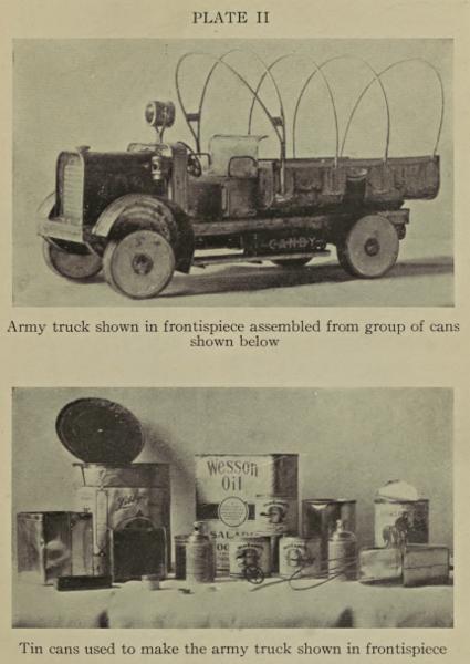
PLATE III
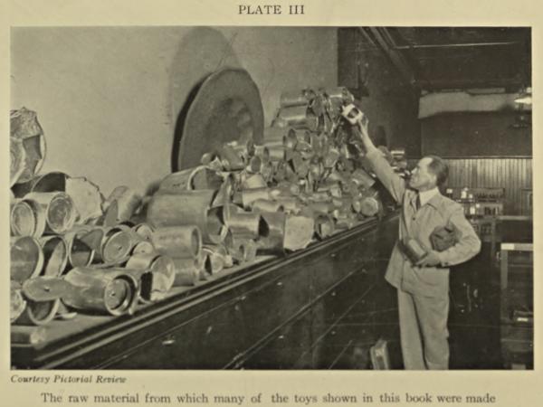
Courtesy Pictorial Review
The raw material from which many of the toys shown in this book were made
PLATE IV
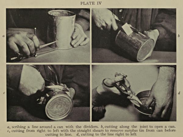
a, scribing a line around a can with the dividers. b, cutting along the joint to open a can. c, cutting from right to left with the straight shears to remove surplus tin from can before cutting to line. d, cutting to the line right to left
PLATE V
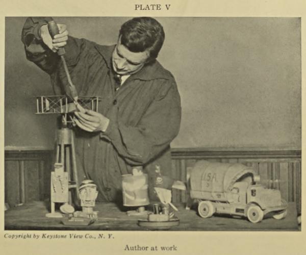
Copyright by Keystone View Co., N. Y.
Author at work
Then using a pair of straight metal shears, cut down each side of the seam or joint in the side of the can to within one-half inch of the horizontal line you have marked with the dividers (see Plate IV, b).
Bend out the narrow strip containing the seam and cut it off with the shears. This will give you an open slot in the side of the can in which the shears may be easily introduced to cut horizontally around it.
Do not try to cut directly on the line marked around the can with the dividers but begin cutting about half an inch above this line and cut completely around the can until you have cut off the whole top part of it. After you have cut away the larger portion of the metal, the narrow strip remaining above the line may be easily cut away as it curls up out of the way as it is cut by the shears.
The can should be held in the left hand with the open end or top toward you (see Plate IV, c). Be sure you hold the can in this manner. With the tin snips held in the right hand, start cutting toward the left hand always when cutting around a can or box. Bend the tin out of the way as you cut. You will find that it is impossible to cut in a straight line or to make a continuous unbroken cut while cutting away a large portion of the can. But, after the larger piece is out of the way, the narrow strip remaining above the line may be easily cut away if you cut toward your left hand and hold the open[24] end of the can toward you. It is impossible to cut a straight line around a cylindrical form with a pair of straight shears unless the shears cut from right to left and that part of the metal which is cut away is nearest the operator.
The beginner will perhaps find it easier to handle the cans if a pair of old thin kid gloves are worn.
If one can afford it, the pair of double cutting shears such as are listed in the supplementary tools on page 31 are excellent things to have for opening and cutting around cans. These shears have three blades, and one blade cutting between two fixed blades cuts away a narrow strip of tin as the shears are worked along in such a manner that a straight line may be followed around a can at the first cutting. The point of the single blade may be punched into the side of a can and the cut started around the can at any point. If many cans are to be cut down, these double cutting shears will save much time and trouble. However, the straight shears will answer well enough, if the above directions are carefully followed.
Be sure to try not to cut to the line the first time you cut around a can. Cut away the larger part first and then cut to the line when there is only a narrow strip to cut away. Do not mind if the first piece cut away looks very rough and jagged. It may be a little difficult at first, but patience and practice will[25] soon make it quite easy to cut open a can in this manner, using a pair of ordinary straight shears.
Cut away the top of the can or the rolled edge adhering to that part of the can which is cut away; trim away all jagged edges; place flat on the bench or anvil and flatten out the tin with light blows of a wooden mallet. Lay this tin aside until needed.
I find it convenient to cut away the top or rolled edge of large round cans before cutting around them near the bottom, as then it is easy to bend the comparatively large sheet of tin out of the way of the shears as I cut around the can at the bottom. A large pair of shears is very convenient for opening large cans, but small ones will do if intelligently used.
When cutting metal with a pair of shears, always remember that the shears cut more powerfully near the joint or bolt, particularly when cutting through a folded seam or soldered joint. Keep the shears well oiled and have them sharpened by a competent mechanic when they become dull.
When cutting narrow strips of tin, be careful not to get the tin jammed between the shear blades so that the blades are forced apart sideways. Keep the bolt tightened so that the blades fit closely together.
One might suppose that cut or burned fingers would be plentiful in a large class of tin toy makers, but such has not proved to be the case. There have[26] been surprisingly few accidents of this sort and none of them at all serious.
One soon learns how to handle tin so as to avoid rough or sharp edges and that a soldering copper is provided with an ample handle so that it may be safely and easily handled when hot.
Some of the students found that old kid gloves with parts of the fingers cut off afforded protection to hands that were not used to shop work.
A bottle of iodine was kept handy and such slight cuts that were encountered were immediately washed with cold water and iodine applied to the cut which was then lightly bandaged. This treatment proved most effective and no ill effects resulted.
A mixture of pure linseed oil and lime water may be obtained at any druggists and this is a very effective remedy for burns. The solution should be well shaken up and applied directly to the burn which should then be bandaged with bandages wet with the mixture.
Common brown laundry soap worked up into a thick lather is an excellent remedy for slight burns.
Care and patience used in handling the tin and the tools will leave very little use for the above remedies in the shop.
The various problems presented in this book of tin can toys should be worked out in the order in which they are presented as each one bears a definite[27] relation to the others. Be sure to work out the simpler problems first—even if you have had considerable experience in other forms of metal working. A number of processes particularly adapted to working tin are used in making tin can toys.
While these processes are very simple, they are somewhat unlike those involved in copper working and jewelry making, though more closely allied to the commercial metal work of to-day.
TOOL LISTS AND COSTS—LAYING OUT AND MARKING OFF THE WORK—SHOP APPLIANCES
In this chapter the names and approximate costs of the tools and appliances are given and also suggestions as to fitting up the shop for working with the cans. Various methods are suggested for laying out the work with the ruler, square and dividers.
It must be remembered that tool prices are not fixed and that the prices quoted in the following lists are the market prices of to-day, July 29, 1918. At present, tools are much higher in price than usual owing to conditions brought about by the war. Tool prices vary with market conditions.
The tools listed may be bought at any good hardware store or ordered from the catalogues of any of the large mail order houses (except the Wooden Roofing Folder and the Forming Mallet). While the folder is not absolutely necessary for folding up angles in the tin, it is much better to have one to make the numerous angles employed in tin work than to attempt folding by hand, and particularly when long angles are to be made for lanterns, towers,[29] automobile chassis and the like. In fact, it is in almost constant use.
The wooden roofing folder is not carried in stock by hardware and mail order houses, but it may be ordered from a dealer in tin-smiths’ or sheet metal workers’ tools. Any good tinner or plumber will tell you where to order one.
The forming mallet is easily made from a block of maple or a piece of broom handle as described under Shop Appliances.
It is taken for granted that such simple tools as rulers and pencils are at hand.
| 1 soldering copper, weight 1 lb. (1 lb. actual weight of copper end) | $ .75 |
| 1 wooden handle for copper | .10 |
| 1 pair tinners’ shears, 8 or 10 inch | .85 |
| 1 pair flat-nose pliers, 4 inch | .45 |
| 1 pair round-nose pliers, 4 inch | .45 |
| 1 pair dividers, 6 inch | 1.25 |
| 1 small riveting or tack hammer | .40 |
| 1 half round file, smooth milled cut, 8 to 10 inch | .20 |
| 1 wooden mallet, 3 inch face | .25 |
| 1 box of soldering paste | .25 |
| 1 bar of soft solder | 1.25 |
| 2 lbs. soft solder wire | 1.20 |
| 1 wooden forming mallet (home made) | |
| 1 wooden roofing folder (optional) | 4.50 |
| (Roofing folder may be obtained only from dealer in tinners’ tools.) | |
| 1 vise (3 inch jaws) | $3.50 to 5.00 |
| 1 try square, 6 inch | .65 |
Materials Needed Aside from the Cans.—Galvanized wire, 10 or 15 feet each of the following diameters: ⅟₁₆, ⅛, ³⁄₁₆, ¼ (if impossible to obtain all these diameters, get ⅛ inch or larger). Wire nails, about ½ lb. each of the following sizes: 2d, 3d, 4d, 6d, 8d, 10d, 20d (d is the abbreviation for penny). Tinned rivets, several dozen of the smallest size (a box containing one gross is about as cheap as six dozen). Can of lye or 2 pounds of washing soda. For heating the soldering copper, a heater of some kind, such as a blue flame kerosene stove, gas furnace or common one-burner gas stove, charcoal furnace, or gasoline plumbers’ torch with attachments for holding copper. A large can or pail, or an old wash boiler for holding the hot lye solution.
Supplementary Tool List.—The tools named in this list will be found very convenient for making the more advanced models, particularly the hand drill and the twist drills which are used with the hand drill. The supplementary tools are by no means necessary for making the tin can toys, but if one can afford to get them, they will be found extremely convenient. However, almost any of the models may be made with the tools listed on page 29, if one is sufficiently skillful in the use of them. The more work one does with tools the fewer tools one needs if the tools are intelligently used.
The tools in both lists should be purchased, if possible, as they are all tools commonly used in metal working shops. Purchase the tools listed on page 29[31] first and go as far as possible with them, and then purchase as many of the supplementary tools as possible when you need them.
Except when noted otherwise, these tools may be purchased at any good hardware store.
| 1 hand drill, capacity ⅟₃₂ to ³⁄₁₆ inch drills | $1.75 |
| 4 twist drills, ⅟₁₆, ⅛, ³⁄₁₆, ¼ inch diameters | $ .10 to .20 |
| 1 pair large tinners’ shears, 12 or 16 inch | 1.50 |
| 1 pair curved tinners’ shears, 8 inch | 1.25 |
| 1 pair double cutting shears, 8 inch (optional) | 1.85 |
| 1 pair side cutting pliers, 5 inch | .75 |
| 1 pair spring dividers, 6 inch | .75 |
| 1 pair outside calipers, 6 inch | .75 |
| (Spring dividers and outside calipers may sometimes be obtained at the 5-and-10 Cent Stores.) | |
| 1 small soldering copper, weight about 4 ounces | .35 |
| 1 half-round file, 8 inches (fine cut) | .25 |
| 1 round file, 8 inches long, ¼ inch diameter | .20 |
| 1 small cold chisel, ¼ inch in width at cutting edge | .15 |
| 1 large cold chisel, ¾ inch at cutting edge | .25 |
| (An old wood cutting chisel is just as good for cutting tin.) | |
| 3 nail sets, ⅟₁₆, ⅛, ³⁄₁₆ inch in diameter at point, each | .10 |
| (These nail sets may also be used as punches or ground to chisel points. Small chisels and nail sets may be obtained at the 5-and-10 Cent Stores.) | |
| 1 carpenters’ scratch awl | .25 |
| (An ice pick of the same type will do as well.) | |
| 6 small clamps of different sizes | .10 to .25 |
| (These clamps may usually be found at the 5-and-10 Cent Stores.) | |
| 1 hatchet stake, 9-inch blade | 1.75 |
| (Obtained only from tinners’ and sheet metal workers’ supply houses. A small substitute may be made from a 10-cent hatchet. Purchase the hatchet stake if you can afford it.) | |
| 1 bench drill | $7.50 |
| (The bench drill is by no means necessary for any of the models described in this book, but it is a very convenient tool to have in the shop. With this tool, a hole may always be bored at right angles to the work. The hand drill will answer every purpose if one cannot afford this tool.) |
Laying Out and Marking Off the Work.—Before attempting to begin actual work with the cans, it may be well to consider various ways of measuring to certain dimensions and transferring these measurements to the surface of the tin, and laying out and marking off the work for cutting, folding, etc.
The tools needed for this work are few and simple. A ruler, a marking awl, a small try square, and a pair of spring dividers are all one needs for this part of the work. The ruler may be of wood or metal and should be at least 12 inches in length with the inch divisions marked on it. A plain straight rule of hard wood such as is used in the grade schools will do very well.
PLATE VI
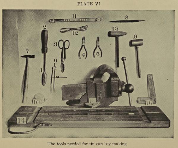
The tools needed for tin can toy making
The marking awl may be purchased at any good tool house or hardware store or an ice pick will do very well if sharpened to a good point so that a line may be easily scratched in the surface of the tin with the point. A large stiff needle may be forced in a pen handle to make an excellent marking awl or a common steel knitting needle may be used if the[33] point is sufficiently sharp. Metal workers always scratch their dimension lines in the surface of the metal as pencil lines are easily rubbed away by the hands when working with the metal.
The try square should be about six inches long at the blade or measuring side, and should be entirely constructed of metal and the measuring blade should be marked off in inches and fractions thereof. Good try squares may frequently be purchased in the 5 and 10 cent stores and these are quite accurate enough for the purpose. The spring dividers should be about 6 inches in length. These dividers are held open by the strong spring in the top and are opened and closed by a nut acting on the screw thread. Do not purchase the heavy dividers or compass commonly used by carpenters as these are not as capable of the small adjustments as are the spring dividers. The spring dividers may sometimes be found at the 5 and 10 cent stores and may always be found at good hardware stores and tool houses.
All the tools used for laying out and marking off the work are plainly shown (Plate VI).
Laying Out Work.—It should be borne in mind that a little time spent in carefully measuring, laying out and marking off the work will make a great difference in the finished appearance of that work, so that these simple operations should not be slighted.
The steel square should always be used in laying out rectangular work: lines that are supposed to be[34] at right angles or “square.” Work that is not carefully laid out or square will not fit together neatly if it fits at all.
One of the first things that one has to do in the tin can work is to trim up a piece of tin that is taken from the side of a can and flattened out.
Suppose that such a piece of tin has been cut from a can and flattened out, the edges of such a piece of tin are rather jagged and the whole piece should be trimmed off square before trying to use the tin for various purposes.
First place the ruler as near to the upper edge of the tin as possible and so as not to include any of the jagged cuts. Hold the ruler down firmly and draw the point of the marking awl along the edge of the ruler until a straight line is scratched along the edge of the tin. The surplus tin above this line should be cut away with the metal shears by cutting along from right to left so that the narrow and jagged strip of tin is curled up out of the way by the shears as it is cut. When the surplus tin is cut away you should have a straight clean edge at which to begin the marking operations.
Using the Try Square.—Next, the two ends of the piece of tin should be squared off using the try square for squaring up the ends as follows: Place the heavy solid part of the square firmly against the freshly cut straight edge of the tin, near one end in such a manner that the blade of the square with the[35] inch divisions marked on it lays squarely across the tin, and as near as possible to the end of the piece but not including any of the jagged cuts. The position of the square is shown in Fig. 1.
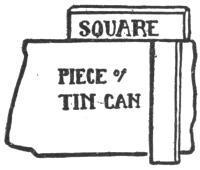
Fig. 1.
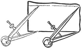
Fig. 2.
When the square is in position, mark a line across the tin with the scratch awl held closely to the blade. Cut away the extra tin and you have two sides of your piece of tin squared. Proceed in the same manner to trim off the other end. The remaining or long side of the piece may be squared up either by using the ruler or the spring dividers. The strip of tin that you have squared up on three sides will probably be narrower at one end than at the other. Measure the width of the narrow end with the ruler and then measure off this same distance at the opposite end and mark it with the scratch awl. Use the ruler to connect the two measuring points and scratch a line in the tin by drawing the scratch awl along the edge of the ruler. Cut away the surplus tin and your piece of tin should be squared.
The spring dividers may be opened so that the points rest exactly on each corner of the narrowest end of the strips of tin. Then the dividers are moved to the opposite end of the strip and the lower end or point of the dividers moved back and forth slightly until a slight scratch is made in the surface of the tin to indicate the measuring point. The position of the dividers is shown in Fig. 2. The ruler is used to connect the two measuring points and a line scratched between them.
Small strips of tin may be marked off entirely by the dividers by setting the dividers to the required dimension, placing the dividers so that one point rests against one edge of the strip to be marked off and then drawing the dividers along in such a manner that the point of the dividers that rests on the tin will scratch a line parallel to the edge. The edge of the tin that the point of the dividers rests against must, of course, be cut straight before beginning the marking operations. The strip thus marked off may be cut away and another one marked off in the same manner until the required number of strips is cut.
Suppose that four strips are to be cut, each strip to measure one by ten inches. Square up a piece of tin to measure four by ten inches. Open the dividers so that the points are exactly one inch apart. Rest one point of the dividers against one edge of the tin as shown in Fig. 2 and draw it along the entire length of the tin so as to scratch a line parallel to[37] the edge. Cut off this strip, taking care to make a straight cut and then mark off another strip and cut it off, and so on until all four strips are cut. This method of using the dividers for marking is more accurate and much easier than that of using a ruler to measure off each strip, and certainly more rapid.
Finding Wheel Centers with the Dividers.—When making wheels of tin cans, some easy method must be used to find the center of the wheel in order to punch or bore a hole for the axle so that the axle may be placed as near the center of the wheel as possible, and so that the wheel will run true once it is placed on the axle.
The dividers may be used for this operation which is very simple. The can is first made up into wheel form as described in Chapter X, page 108. When the wheel is soldered together lay it flat on the bench. Open the dividers so that one point rests against the rim of the wheel or against the rolled edge of the can forming the rim of the wheel. If the wheel is made of a can that has a cap soldered on each end and this cap forms the end of the can (such as the small cans that are used for evaporated milk), then the one leg of the dividers may be rested in the slight line or depression just inside the rim that is invariably found in this can. Open the dividers so that the other point rests as near the center as you can guess it. When the dividers are set to dimension and are in position on the wheel[38] as shown in Fig. 3, then move the point of the dividers that is near the center of the wheel slightly back and forth so that it describes a slight arc and scratches it in the surface of the can and the other point of the divider is held at the point near the rim of the wheel during this operation. Then move the dividers directly across the wheel still set at the same dimension, placing one point against the rim or in the depressed line and describing a slight arc in the tin as before. Set the dividers at right angles to the first two marking points having the dividers still opened to the same dimension as at first and describe another arc. Set the dividers directly across from this point and describe another arc. The wheel should then resemble Fig. 4, the four arcs forming sort of a pillow shape as shown. Draw lines diametrically across connecting each corner of the pillow as shown and where these lines cross is the center of the wheel.
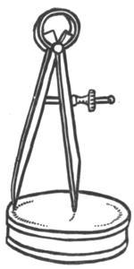
Fig. 3.
If one is so fortunate as to possess a tool called a surface gauge, it will be found very handy for[39] marking or scribing lines parallel to the base of cans. This tool consists of a base of metal in which is fixed an upright post also of metal. An adjustable scriber or needle is fixed to this post so that it may be lowered or raised and set in position as desired. The point is adjusted to the required height and placed against the side of the can or surface to be marked, the operation being conducted on a flat level surface. The can is simply turned against the fixed scriber point until it is entirely marked around. The advantage of the surface gauge over the dividers for this operation is that the scriber point is held rigidly at a fixed dimension above the base of the can while the dividers must be held firmly in place by the hand. However, the dividers will do very well for this operation after a little practice.
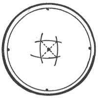
Fig. 4.
Homemade Substitutes for Expensive Tools.—The tool of first importance in any metal working shop is a good vise. There is no substitute for this tool and a good one that measures three or three and a half inches across the jaws should be purchased[40] from a reliable tool dealer. The next tool of importance is some form of anvil or anvils for flattening or rounding the tin. A small bench anvil may be purchased from the tool dealer. These are much like a blacksmith’s anvil with a flat face and a conical horn and are made of iron and steel. The large mail order houses offer various small anvils of cast iron for farm use and these are excellent for the tin shop.
Excellent substitutes for these anvils are easily made from old flat irons and pieces of gas or water pipe. Short lengths of iron and steel bars may be picked up about any junk pile, and these are very useful to form the tin over.
The Flat Iron Anvil.—An old flat iron, the kind with the handle attached, may be found about almost any household. The handle should be broken off as close to the top of the iron as possible. Use a hammer and cold chisel for this and cut the handle ends deeply all around where they join the iron. When they are deeply nicked, several sharp blows from a large hammer should break the handle away.
File away all roughness until the iron will set level with the smooth or ironing face uppermost. Then you have an excellent flat hard surface for straightening out tin or wire.
Pipe and Bar Anvils.—Short lengths of iron pipe, round and square iron and steel bars of various diameters may be held in the vise jaws and used to[41] form the work over. Large wire nails may also be used for this purpose.
The smaller sizes, such as ¼, ⅜, or ½ inch in diameter, should be solid iron or steel bars 8 or 10 inches in length, as small pipe crushes and bends rather easily in the vise. Larger sizes, such as ¾, ½, 1 or 2 inches in diameter, are better made of pipe as they are lighter and easier to handle and also easier to obtain.
Get all the sizes suggested if possible and as many short pieces of square or flat bars as you find convenient to store away about the shop. They will come in very usefully for bending or forming operations. The method of holding them in the vise is plainly shown on page 89, Fig. 26.
If you have plenty of bench room and are handy with tools, several of the most used sizes of pipe and bars may be clamped or bolted directly to the bench with wooden or metal holding strips. The larger sizes, such as ¾, 1, 1½, 2 and 3 inches in diameter, will be found very convenient if fastened to the bench in this manner.
The Bench.—The shop bench should be about 31 inches in height. The top of the bench should be about 2½ by 6 feet or larger if possible, and may easily be built by any one familiar with tools. The top should be made of maple about 1½ inches thick. If one cannot afford this bench a common kitchen table makes an excellent substitute. A good strong[42] table of this sort may be purchased at any house-furnishing store. These tables are furnished with a large drawer in which small tools may be kept.
If much of the tin work is done, it will prove advantageous to have some light wooden shelves or racks built about the walls of the shop to store the various sized cans where they may be easily seen and reached.
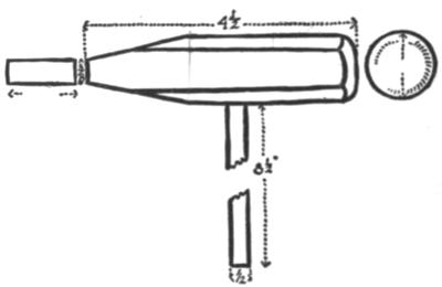
Fig. 5.
The Forming Mallet.—The special forming mallet designed by the author will have to be made. It was designed especially for work with the tin cans. It is very simple and easily made of maple by any carpenter. One end is a slightly rounded dome shape and the other is in the form of a blunt wedge. The dimensions and general shape of the mallet are[43] shown in Fig. 5. The handle may be made of a piece of ½-inch dowel rod. A substitute for this mallet may be made of a piece of broom handle the end of which is already rounded to about the proper curve. Measure off 4½ inches from the rounded end of the broom handle and saw it off. Bore a ½-inch hole through the center of the piece to fit the piece of dowel rod used for the handle. Whittle down the end to a blunt wedge shape leaving it about ⅜ inch thick at the end. The rounded end may be left as it is.
A piece of ½-inch maple dowel may be picked up in any carpenter shop. This should be 8½ inches long. It should be driven into the hole drilled for it in the mallet, taking care not to split the mallet in so doing. If the broom handle is rather small in diameter it would probably be better to use a piece of ⁷⁄₁₆-or ⅜-inch dowel for the handle. A small nail or brad may be driven through the mallet and handle to secure it in place.
CUTTING THE CAN TO SIZE FOR BISCUIT CUTTER—PUNCHING A HOLE IN TIN—FORMING THE HANDLE—FOLDING—MAKING A SUGAR SCOOP BY THE SAME METHOD
A biscuit cutter is about the simplest thing that may be made from a tin can. It is an excellent thing to begin with as it is so simple and involves three very essential operations in the tin can work: cutting the can to size, forming the handle, and lastly, soldering (see Plate VII, a).
Select a good bright, clean can about 2½ inches in diameter; a baking powder can or a small soup can will do.
Tin cans are usually made up in two ways. One method is to solder on flanged ends, such as condensed or evaporated milk cans, and the other method is to roll the edges of the can together at each end, using no solder. When looked at closely, the two different types of can are easily told apart. A rolled rim can should be used for the biscuit cutter as it is stronger than the can with the soldered ends.
PLATE VII
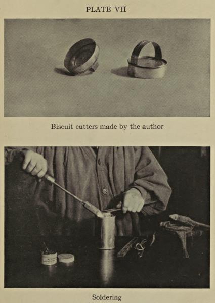
Biscuit cutters made by the author
Soldering
Cutting the Can to Size for Biscuit Cutter.—The biscuit cutter should be about ¾ inch deep at the[45] cutting edge. Set the dividers to this dimension and proceed to scribe a line around the can parallel to the base and ¾ inch above the rolled rim of the bottom. This simple scribing operation is described in Chapter I, page 22.
The method of cutting into the can and around the scribed line is very simple and is also described in Chapter I.
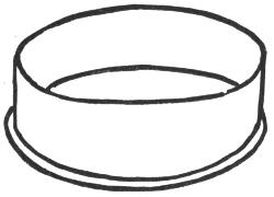
Fig. 6.
When you have cut the can down to the required dimension, it should appear as shown in Fig. 6. The biscuit cutter may be slightly out of shape after the cutting operation, but this may be easily remedied by placing the biscuit cutter on a small round anvil held in the vise and by tapping it gently with a flat wooden mallet, turning the cutter slowly around on the anvil during the hammering as shown in Fig. 7. Be sure to turn the biscuit cutter slowly around and around the anvil as it is hammered with the mallet. It will soon become round if hammered gently.
Next take a small flat file, one with very fine teeth, usually called a smooth milled file, and with this smooth down any roughness left by the metal shears at the edge of the biscuit cutter. The method[46] of using the file is shown in Fig. 8. It should be held lightly against the work when filing. (Never try to file a piece of tin with a large or roughly toothed file as the coarse teeth will catch on the tin and tear or bend it out of shape.)
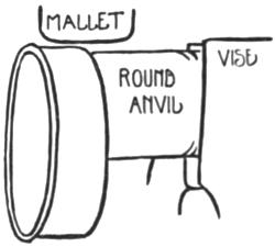
Fig. 7.
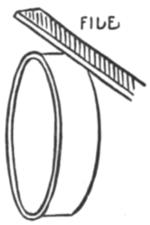
Fig. 8.
Do not try to file the edge of the cutter to a knife fine edge; simply file away the metal raised by the shears when cutting. If it is cleanly cut and filed to the original thickness of the tin, it will cut biscuit dough very well, as the tin is thin.
Punching a Hole in Tin.—A hole should be punched in the top of the biscuit cutter to admit air, as the biscuit dough is apt to stick in the cutter by the vacuum formed unless an air vent is provided. A small hole about ⅛ inch in diameter will do, but a series of such holes may be punched in if desired.
A punch may be filed up from a wire nail or a regular punch or nail set may be used.
The biscuit cutter is placed over the end of a block of wood held in a vise as shown in Fig. 9, in such a manner that the top of the cutter rests directly on the wood. The punch is placed in the center of the cutter, care being taken to see that the wooden block supports the tin directly under the punch, and then the punch is struck lightly with the hammer until it cuts through the tin.
It may be well to try the punch on a scrap of tin to test it. A clean round hole should result. The punch cuts out a tiny disk of tin and drives it into the wood. The end grain of a wooden block should always be used for punching on.
If a nail is used for a punch, the original point should be filed away. Nail points are usually made in the form of a square pyramid and if these points are driven into a piece of tin a jagged hole will result; such a hole may be used for making a grater for the kitchen, but all other holes should be round and smooth.
To file up a nail for a punch proceed as follows: Place the nail vertically in the vise jaws so that the point projects slightly above the jaws. File the point entirely away until you are filing the entire diameter of the nail and squarely across it.
Then reduce the diameter of the nail at the end you have been filing by filing smoothly around it as[48] shown at A, Fig. 10. See that the edge B is clean and sharp and the nail punch is ready for use. The nail used for a punch should always be somewhat larger in diameter than the punching point, as this will provide for a stronger punch and one not so likely to bend. Regular punches are usually made much thicker in the body than at the point, as may be easily seen by looking at one. If desired, punches may easily be made from nails to cut round, square, or triangular holes.
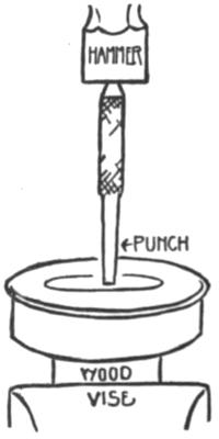
Fig. 9.
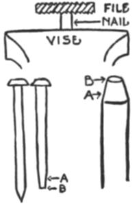
Fig. 10.
It is much better to purchase a regular punch or[49] punches for punching round holes, as these may be purchased for 10 or 15 cents at almost any hardware or 5-and-10 cent store. Several different sizes will prove useful, ⅟₁₆, ⅛, ³⁄₁₆ inches in diameter being the most used sizes. As these punches are made of hardened steel they hold their edges for a long time, but nails are made of a fairly soft steel and when used as punches have to be frequently filed sharp.
Forming the Handle.—After the hole is punched in the top of the biscuit cutter, a suitable handle is the next thing to be made. This handle may be made from the piece of tin cut away when cutting down the can for the biscuit cutter. Cut away any rough or jagged edges and then place this piece of tin on the bench or a flat anvil surface and flatten it out with light mallet strokes. Heavy strokes with a mallet will dent the tin.
Trim away all rough edges including the rolled edge at the top and square up the piece of tin as described on page 34, Chapter II. Mark off a strip of tin 1¼ inches in width and 4 inches long. Cut this strip out and be sure that it is square at the ends. Open the dividers and set the divider points ¼ inch apart and scribe a line ¼ inch inside each of the long sides of the strip. The edges of the strip of tin thus marked off must be turned or folded in so that the edges of the handle will be strengthened and will not cut the hand. These edges may be folded over with a mallet or by the use of a folding[50] machine. The mallet should be used for this first folding operation; the folding machine and its use will be described further along in the book, page 120, Chapter XI.
To fold the edges over with the mallet, proceed as follows: Secure a block of hard wood, maple preferred, the block to be about 3 inches square and 6 inches in length. See to it that the block is cut cleanly and squarely across so that the edges at the end are sharp and at right angles. A maple block of this sort may usually be picked up at any lumber yard or carpenter shop, or a maple log may be secured from the wood pile and trimmed up square. One end of the block may be used to punch on.
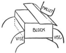
Fig. 11a.
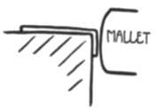
Fig. 11b.
The block is held in the vise as illustrated in Fig. 11 and the tin to be folded is held on the block in such a manner that the line marking the fold is over the edge of the block. Use either a light wooden mallet or the special forming mallet, and[51] with light blows proceed to bend down at the edge and up to the line as illustrated in Fig. 11, a. Begin at one end and work along the line to the other end of the strip of tin. Do not try to turn the tin down at a right angle at once or in one place and then proceed to turn it down at another, but rather hammer lightly along the whole length at the marking line, turning the tin down at a slight angle from the line to the edge and then going back and starting to hammer where you began, turning the tin down at a greater angle and so on until you have turned the edge at right angles as shown in Fig. 11, b. Always bend tin over very gently and evenly, never forcing it violently into place.
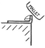
Fig. 12.
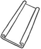
Fig. 13.
Fig. 14.
Reverse the strip of tin on the block so that the part just folded stands vertically at the edge of the block as shown in Fig. 12. Hammer the edge of the tin gently over so that it folds back on itself as shown by the dotted line in Fig. 12.
Do not hammer the tin down hard at the folded[52] edge so that it becomes thin and sharp though doubled. It should be rounded over so as to give a rounded edge. A rounded fold is much stronger than a sharp thin one. When one edge is completely folded over, fold down the other in the same manner, so that both edges of the handle for the biscuit cutter appear as in Fig. 13.
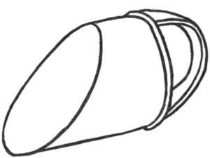
Fig. 15.
When you have successfully turned or folded over the edges to your satisfaction, then proceed to give the whole handle a semi-circular form.
Place a large round wooden mallet or a piece of 1½ or 2-inch pipe in the vise to use as a form over which to round the handle. The folded part should be inside or next the mallet or pipe form shown in Fig. 14. Press the tin down to the form with the[53] palm of the hand so as to round it into shape; it may be completely formed into shape by this method or the rounded end of the special forming mallet may be used to hammer it into shape if the tin should kink during the bending. The mallet blows should be directed toward the center of the strip so as not to thin the edges too much.
Round the handle over until the ends rest inside the rolled rim of the can or biscuit cutter and you are ready to solder the handle in place.
As the soldering is the most important part of the tin work the next two chapters are devoted to it.
The Sugar Scoop.—A useful sugar or flour scoop may be easily made from a small or large can in exactly the same manner as the biscuit cutter, except that the can is cut off slanting instead of square, Fig. 15. The edges of the scoop should not be turned or folded but should be left as cut so as to form a sharp cutting edge that will easily enter sugar or flour. The handle is shaped in exactly the same manner as that of the biscuit cutter.
SOFT SOLDER—SHEET TIN—THE PROCESS OF SOLDERING—HEATING APPARATUS—ELECTRICAL SOLDERING COPPERS—THE COMMON SOLDERING COPPER—FLUXES—TINNING THE COPPER—HEATING
Soft Solder.—When two or more pieces of metal are joined together with a metallic cement, they are said to be soldered.
Sheet tin, of which cans are constructed, is always soldered with soft solder, a mixture of lead and tin, usually 50 per cent. lead and 50 per cent. tin.
This solder is usually supplied in wire or bar form at any hardware or electrical supply house.
Copper, brass, bronze, iron, silver, gold, and practically any metal except aluminum may be soldered with soft solder.
Sheet Tin.—Sheet tin, so-called, really consists of a thin sheet of iron coated on both sides with tin. This coating of tin serves several purposes. It enables the solder to adhere easily; it prevents the iron from rusting; and when the sheet tin is made up into can form, the tin coating protects the contents of the can from chemical action on the iron.
The Process of Soldering.—Soft solder is applied to the metal to be soldered in a molten state and this operation requires considerable heat. When heat is applied to metal it usually oxidizes that metal; that is, dirties it.
Solder will not adhere to oxidized metal. The metal must be protected with a coating called a flux while being soldered. Soldering paste, soldering fluid or “killed acid,” resin, paraffin, heavy oils, and vaseline all serve as fluxes, some better than others. The soldering paste is by far the best, as will be shown later.
Soft solder is applied to the tin, on the point of a hot soldering copper, often wrongly called a “soldering iron.” A soldering copper consists of a pointed bar of copper suitably fixed to an iron shank which is firmly set in a wooden handle. The point of the copper must be well coated with solder or “tinned,” so that when it is heated it will pick up the solder and convey it to the joint to be soldered.
The hot copper, charged with solder, is passed slowly along the joint and as the tin to be soldered receives enough heat from the copper, the solder leaves the copper and adheres to the tin, firmly uniting it.
Heating Apparatus.—Some form of heating apparatus is necessary to heat and maintain the soldering copper at the melting or flowing point of the solder. The copper may be heated in a gas furnace[56] especially made for soldering coppers, or over an ordinary gas stove burner or a common blue flame oil stove, or a charcoal fire, a wood fire burned down to embers, or a plumbers’ gasoline torch, but never in a coal fire. Coal contains too much sulphur which oxidizes the copper and renders it useless for soldering purposes.
The Blue Flame Oil Stove.—For heating the coppers in my country shop, I use a blue flame oil stove, one of the less expensive sort, with the asbestos ring wick and the short removable chimneys. The stove has two burners and will heat from four to six coppers at once. The flames may be regulated nicely so as to give just the required amount of heat and this stove consumes very little kerosene, and, therefore, costs little to operate. In Fig. 16, it will be noticed that there is a curved hood over each stove hole. These hoods may be easily made from part of a large can or of a piece of tin or sheet iron bent into shape. These hoods conserve the heat and throw it about the coppers. I also place a piece of heavy wire netting over the grating of the stove holes to support the coppers and to permit their being laid to one side, out of the intense heat, when not immediately needed.
The blue flame oil stove forms the most satisfactory arrangement for heating coppers that I have ever used in the country. These stoves are easily taken care of and are understood by almost everyone.[57] The directions should be nailed up alongside the stove and carefully followed, particularly as to cleaning the burners once or twice each season.
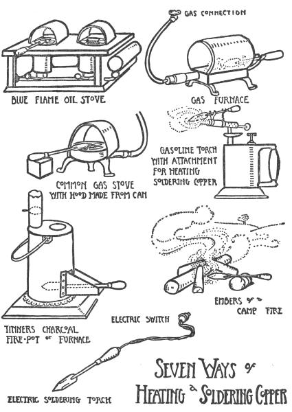
Fig. 16.
The Gasoline Torch.—The plumbers’ gasoline torch is often used by experienced metal workers for heating coppers. In inexperienced hands, this torch is rather a dangerous affair. Only one copper may be heated at a time and it is difficult not to overheat the copper in the fierce roaring flame. The cost of the torch and the cost of operating it are both greater than the blue flame kerosene stove. However, in experienced hands, it is safe enough and very useful about the shop. In using such a torch the directions should be most carefully followed; all joints, filler openings, etc., must be airtight when operating or a disastrous fire or explosion may result. The tiny jet opening in the burner must be kept clean.
The Gas Furnace.—In my winter shop in the city where gas is available, I use the gas furnace shown in Fig. 16. This is a most satisfactory and widely used heater for soldering coppers, as it gives an intense blue flame that may be easily regulated.
When using a heater of this sort, one must be sure that it is lighted correctly or a smoky yellow flame will result. To produce a blue flame, air must be mixed with the gas; just as it is in a bunsen burner or an ordinary gas stove, for that matter. Gas is admitted to the furnace through a small nozzle at the end of the mixing flue near the rubber hose connection. Air is admitted in the slot under the gas nozzle; a movable slide encircles the mixing[59] flue over the slot to control the amount of air admitted. This slide must be tightly closed over the air vent when the gas is first turned on.
To light the heater, close the air inlet tightly, turn the gas on full and apply a lighted match to the burner. A yellow flame will result. Now open the air vent slowly, by pushing the slide forward a little way. The flame will change from yellow to blue and purple as air is admitted. When the flame is blue, it is giving out the most heat and is in the best condition to heat the copper.
If the flame fires back and lights the gas at the brass nozzle over the air inlet, the gas should be turned off until the flame disappears. The air inlet is then closed, and the gas turned on and lighted, and then the air inlet is slowly opened until the flame turns blue. When the furnace is in use, it should be looked at occasionally to see that the flame has not fired back to the nozzle. Once satisfactorily lighted, the heater may be turned up or down as needed. If the flame is turned down very low the air inlet may have to be closed a bit to prevent the flame from firing back. The copper is placed on the rest provided for it over the flame. After the copper is heated to the flowing point of solder, the flame may be turned down or the copper placed to one side of the flame, so that it does not get too hot.
Charcoal and Wood Fires.—When using a charcoal or a wood fire, the copper should be placed at[60] the bottom among the embers. Small charcoal furnaces used for heating soldering coppers may be bought from the dealer in plumbers’ supplies. Charcoal should not be burned in a closed room as the fumes are deadly unless allowed plenty of constantly changing air. These furnaces may be connected with a chimney or burned in a room with windows opened, without danger.
A soldering copper may be heated in the glowing embers of a camp fire or in the embers in a fireplace.
Electrical Soldering Coppers.—The electrically heated copper is ideal for soldering as the heating coil is enclosed within the copper itself, the wire running out through the handle and connecting with an ordinary electric light socket. The heat is maintained at a proper degree for melting the solder; hence it is an ideal equipment for those who can afford it and where electric current is available. The doctors of certain hospitals have recommended electrical coppers for the use of patients in making tin can toys.
An electric soldering copper costs about $7.50 at the present time.
The Common Soldering Copper.—A suitable soldering copper or “iron” may be purchased at any good tool dealer’s or hardware store; it should weigh about one pound for work with the tin cans.
Almost everyone has purchased a small soldering outfit at one time or another and tried to solder[61] the family wash-boiler or some leaky tinware; usually without success. Such outfits are invariably too small for large work or for the tin can toys.
It must be well remembered that the heat flows from the copper into the work, and that the copper has to heat up the work to the melting point of the solder; hence a large copper weighing several pounds is used to solder wash-boilers, tin roofs, etc., and a small copper weighing a few ounces is used for soldering jewelry, etc.
A large copper in expert hands may be used to solder very small work but a small copper may never be used to solder large work together, because the copper not only has to keep the solder melted to the flowing point, but also has to heat the work itself at the joint to the flowing point of the solder before the solder will leave the copper and adhere to the work.
In actual practice, it has been found that a copper weighing one pound is best. After one gets more adept with the copper, it will be found advantageous to have several coppers of different weights. A half pound and also a four ounce copper will be found very convenient for extremely small work. But, do not begin to solder with a copper weighing less than one pound.
Soldering coppers are usually sold in pairs at the large tool dealers, and coppers listed at two pounds really weigh one pound each; when sending[62] in a written order be sure that you specify that the copper is to weigh one pound singly.
A wooden handle especially made for soldering coppers should be purchased at the same time as the copper; these wooden handles are made large to protect the hand from the heat of the iron shank. The handle is usually furnished with a hole of the proper size drilled in it to permit the pointed end of the shank to be driven in the handle easily with a wooden mallet. If the hole is too small, it should be drilled out so that it is nearly as large as the diameter of the shank. The wooden handle must not be split when driven on with the mallet.
Fluxes.—Before tinning the point of the copper, some flux must be obtained, either a soldering paste or soldering fluid “killed acid.”
An excellent soldering paste called “Nokorode” is by far the best flux obtainable. It is inexpensive, a little goes a long way, and it will not rust or corrode the work as is the case with killed acid and some soldering pastes. It may be easily cleaned from the work after soldering and it makes soldering much easier and simpler for the beginner. Nokorode soldering paste may be obtained at any good electrical supply house or hardware store. If they do not stock it, they will get it for you. There is nothing else just as good on the market, but if for any reason you cannot obtain this particular brand, be[63] sure that any soldering paste you buy is plainly labelled that it will not corrode the work.
Soldering fluid or killed acid is made of muriatic acid in which is dissolved all the pure zinc that it will hold in solution. This fluid is much used by tinners and is certainly an excellent soldering flux, but not nearly as good as the soldering paste for our purposes. However, it is very useful in the shop to dip the tinned point of the hot copper into it to remove the oxide or dirt formed after the copper has been in use for some time. The solder will stick to the point much better after the copper has been cleaned in this manner.
Directions for making the killed acid and the use of other soldering fluxes will be found on page 68.
Tinning the Copper.—Having procured the soldering copper and handle, some flux and soft solder, and having fixed up some sort of heating apparatus, the next step toward soldering is to coat the point of the copper with solder: this is called tinning the copper.
Fix the copper firmly in a vise if one is at hand, as illustrated in Fig. 17. Then file each of the four faces of the point of the copper bright and clean with a flat file. It is better to use an old file for this purpose—one with rather coarse teeth. It will be observed that the copper is placed slantwise in the vise so as to bring one face of the square[64] pyramid parallel with the vise jaws; this position permits filing in a natural horizontal position.
Each face of the point should be rounded slightly toward the point.
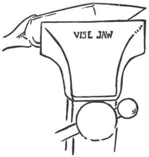
Fig. 17.
If a vise is not available, the copper may be held against the edge of the bench with one hand and the point filed clean and bright with the file held in the other, or a coarse sheet of emery cloth may be placed[65] flat on the table and each face of the point rubbed bright on it. A file is by far the best for this purpose, however, and if it is chalked before using, the copper filed away will not clog it.
When the copper is clean and bright at the point each face should be thoroughly covered with a thin film of soldering paste or dipped into the soldering acid.
The copper should then be placed in the fire and heated to the melting point of the solder.
Heating.—While the copper is heating get ready a piece of tin about 2 by 4 inches—any clean flat scrap or part of a can will do. Spread a little soldering paste into the center of the tin and lay it on the bench near the heating apparatus. A few drops of killed acid may be placed on the tin instead of the paste, if the acid is to be used.
After a few minutes heating the copper should be removed from the fire and the end of a strip of solder touched to the point. If the solder melts quickly and easily against the point the copper is ready to tin; if it melts very slowly, “slushy”, the copper should be returned to the fire and heated a bit more. The copper should never be heated red hot under any circumstances; this must be borne in mind. If the copper is heated to a red heat, the soldering paste will be burned off and its action destroyed, for a red hot copper will not pick up[66] solder, nor may it be tinned again until the copper is cool and refiled bright and clean, recoated with flux and reheated. If the copper is heated red hot after the point is tinned, the tinning is burned from the point and solder will not stick to it until it has been cooled, refiled and retinned.
This is the most important point to remember about soldering and is the cause of many failures. Remember that soldering is impossible without a flux to keep the metal clean when it is hot; too much heat will burn soldering paste or killed acid away; the tinning and the solder adhering to the point will be burned or oxidized and rendered brittle and useless.
A heat that will melt the solder almost instantly and cause it to flow with a brilliant glistening color should be maintained at all times when the copper is employed for soldering. This is never a red heat.
When the copper is first heated to be tinned, it should be removed from the fire when it melts the solder easily, and several large drops of solder should then be melted from the bar or strip of solder onto the piece of tin placed by the fire and on which some soldering paste or acid has been spread. Rub each face of the point of the copper into the solder on the tin until each face is thoroughly covered with a bright coating of solder. Hold each face flatly down against the solder on the tin during the rubbing process. The copper may[67] have to be heated once or twice by the beginner, as it may get too cool to melt the solder easily. As soon as the solder begins to work stiffly, “slushy,” and looks gray instead of glistening, it is time to reheat the copper.
An old piece of soft cotton cloth, such as a stocking, on which is sprinkled a little powdered sal-ammoniac is an excellent thing to keep handy when soldering or tinning. The tin coating of the point of the copper should be rubbed on this cloth where the sal-ammoniac is sprinkled, when the copper is hot. This will be found to keep the copper in excellent condition. The sal-ammoniac removes the oxide from the tinning and brightens it up generally about the point.
The tinning will last much longer on the copper if it is dipped occasionally into the soldering paste or acid while hot. This is particularly true if the copper has been a bit overheated.
When the tinning shows signs of wearing off and the copper does not pick up solder readily, it must be retinned, filed, fluxed, heated, and rubbed on the solder which has been put on the tin first used for this purpose. This piece of tin should be kept about the bench, as the copper will have to be retinned frequently. Always remember that the copper will not carry solder to the work unless it is well tinned.
If an electrical soldering copper is used it is usually furnished already tinned at the point, so that it[68] is ready for use as soon as it is connected to a suitable electric socket and the current turned on. The heating coil inside the copper will soon heat it up to the melting point of the solder. After heating, it may be treated as a common copper, wiped occasionally on the cotton cloth and retinned when the tinning is worn away. An electrical copper should never be placed in a vise for filing, but should be held against the bench and filed carefully. A vise is apt to crush the hollow copper and injure the heating coil inside. These coppers should never be placed in a fire or heated in any way except by the electric current.
Electrical coppers do not need as much attention as an ordinary copper for the even heat supplied by the current keeps the copper heated to the flowing point of the solder and is incapable of heating beyond this temperature.
Soldering fluid may be very simply made as follows: Pure zinc is dissolved in muriatic acid until the acid will not dissolve any more of the zinc. The solution thus obtained is then allowed to stand for a time and is then strained through a cloth and poured into a bottle which is kept tightly corked when not in use.
First purchase about six ounces of muriatic acid[69] from a druggist. Take care not to spill any of this acid on the hands or clothes. Next get some pure sheet zinc. The sheet zinc employed for stove mats as it is sold in the plumbers’ shops is not suitable for making soldering fluid, as this form of zinc is alloyed with other metals. Pure zinc may be very easily obtained from old dry batteries which may be found anywhere.
Remove the paper covering from the battery and crack it open with a hammer—remove the carbon from the center of the battery and dump out all the powdered material. Soak the zinc covering of the battery in warm water to remove any paper or material adhering to the zinc and then cut the zinc into pieces about ¼ inch square.
Find an old tea cup or earthen-ware marmalade jar and pour into it about half a teacupful of the muriatic acid. Set the vessel containing the acid out of doors or near an open window and away from all steel tools, so that the fumes of the acid may escape and not be breathed into the lungs or rust any tools.
Pour a small handful of the zinc cuttings into the acid. The acid will attack them at once and a strong bubbling action will result. When the bubbling action dies down add more zinc cuttings—about every fifteen minutes. When the acid shows no sign of attacking the zinc as it is added, the acid is said to be “killed” and the soldering fluid is made. It may be used at once if necessary, but it[70] will be much better if it is allowed to stand over night with the zinc residue left in it. It is then strained through a piece of muslin cloth into another cup or jar and the fluid is ready for use.
Soldering fluid may be kept in a wide-mouthed glass bottle or a marmalade jar; either vessel must be tightly corked when not in use. This soldering fluid may be used as a flux for any soft soldering operation in place of the soldering paste, but it is not as satisfactory a flux for the tin can work as the paste. The best use for it in connection with the tin can toys is to keep it to dip the point of the hot copper in occasionally to clean the tinning at the point of the copper.
While the prepared soldering paste is best for all soldering operations connected with the tin work, other fluxes may be used if nothing better is at hand. These are resin, olive oil, cottonseed oil, automobile lubricating oil, and paraffin; but these fluxes are not very satisfactory in inexperienced hands. The soldering paste is best for all soldering operations.
PREPARING A JOINT FOR SOLDERING—CLEANING AND SCRAPING—SOLDERING A PRACTICE PIECE—SOLDERING THE HANDLE TO THE BISCUIT CUTTER—A SECOND PRACTICE PIECE—ANOTHER METHOD OF APPLYING SOLDER
Cleaning and Scraping.—If the copper is thoroughly tinned and the heater and materials are ready for use as described in Chapter IV, then several practice pieces should be soldered together before attempting a joining on any real work you may have ready to solder.
If the tin is bright and clean, it need not be scraped at the joint where the solder is to go. Rusty spots should be scraped bright if in the path of the solder. Paper, labels or paint must be cleaned away. If a can has been well rinsed with hot water when the contents are emptied, it will present no difficulties to the soldering, but a can that has been emptied but not rinsed presents a more difficult surface to solder; particularly tomato, fruit, or condensed milk cans. This, of course, applies only to the inside of these cans. Tobacco, coffee, cocoa, tea cans and the like offer no resistance to the solder without washing.[72] The yellow lacquer used to line some cans need not be scraped off. Solder will adhere well to tin so treated, but paper, paint, etc., must be scraped from the path of the solder. The scraped part need only be a quarter of an inch in width on each side of the joint; the rest of the paper labels or paint will be removed in the hot lye bath used before painting the can.
The scraping may be done with an old knife, or a regular scraper furnished by the dealer in tinners’ tools as illustrated on page 202, Chapter XXI.
When scraping the tin bright, do not scrape it so hard that all the tin will be scraped away from the inner sheet of iron, as solder will stick to tin much better than to iron. If the tin is not very dirty, a piece of emery cloth or sand paper may be used to clean the joint.
Paint cans, cans that have contained stove blacking, rubber cement, varnish, shellac, etc., should be thoroughly boiled in a strong lye bath before soldering; paint is usually made of oxides and oxides are a sure preventive of soldering. The lye bath is made by adding two heaping tablespoonfuls of lye or washing soda to the gallon of boiling water. Cans boiled in this solution for five minutes will be thoroughly cleaned and free from paint, paper labels, and practically anything likely to be found inside or outside of a can. The lye or washing soda may be obtained at any grocery store. Care should[73] be taken not to get any of the lye solution on the hands or the clothes as it is very caustic and will burn the hands and ruin the clothes if not immediately washed off. The work should be handled with a wire hook while in the bath and well rinsed with water when removed from it. The same lye bath is used before paint is applied to tin work, when all forming, soldering, riveting, etc., is done. It removes the flux, acid, and finger marks, leaving a clean surface on which to paint.
Soldering a Practice Piece.—For practice in soldering, an angle joint is a good thing to begin with; something that is small and easily held in position while being soldered. As I have already described the forming up of a biscuit cutter to the point of soldering it together, a practice piece resembling it will be an excellent thing with which to begin.
Cut a narrow strip of tin about 1 inch wide and 4 inches long and a flat piece of tin about 2 by 3 inches. Be sure that the ends of the narrow strip are cut squarely across, using the square if necessary. (See chapter on “Laying Out Work,” page 32.) See to it that both pieces are well flattened out and smooth.
Bend the narrow strip into a semi-circular form, like the biscuit cutter you have already to solder and stand this piece in position on the larger flat piece of tin.
Now lay the piece near the soldering copper heater, on the wooden bench; be sure to place it on wood, not on a part of the vise or any other metal that may be convenient. Iron, stone or brick will absorb too much heat from the tin if directly under and in contact with it, and thus prevent soldering.
Apply a small amount of soldering paste to each joint as indicated in Fig. 18. The paste may be applied with a small flat stick of wood such as a match stick shaved down to a long, thin, wedge point.
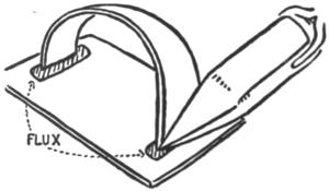
Fig. 18.
Killed acid or soldering fluid is usually applied with a small camel’s-hair brush set in a quill; sometimes a chicken feather is used for this purpose.
The flux, whether paste or acid, should be applied sparingly, but be sure that enough is applied to thoroughly cover the joint, as if it were painted on both sides of the metal where it joins.
See to it that the copper is well tinned and heated until it will melt and take up a good sized drop of solder at the point when held against a bar or strip of solder. Wire or strip solder is much easier for the beginner to handle than the heavier bar. It melts far more easily, as it is smaller.
If bar solder is used, place it on an anvil or stone and hammer one end out, until it is about ⅛ inch thick and much wider than the original bar. It will melt off much more quickly when thinned out.
Hold the semi-circular piece in position with the left hand and with the right bring the hot copper charged with molten solder at the tinned point and fit the point of the copper closely into the angle formed by the joint, moving the copper very slowly along the joint, starting at one side and finishing at the other.
When each side of the joint is thoroughly heated up to the melting point of the solder, some of the solder will leave the copper and flow into and over the joint; so that when starting to solder a joint the copper should be allowed to rest a moment where the soldering is to be started. The tin is then heated up and when the solder starts to flow into the joint, the copper is drawn slowly along, heating up the tin, and as it travels flowing the solder into the joint.
The following points should be well remembered when soldering:
That the tin, to be soldered, must be heated up to[76] the melting point of the solder before the solder will leave the copper and adhere to the tin.
That the copper supplies the heat to the tin and that the tin will not be heated unless the copper is kept in contact with it long enough to heat it. Enough of the copper should be in contact with the tin to be soldered for the heat to flow quickly into the tin, see Fig. 18. Do not merely touch the point of the copper to the joint and expect it to heat that joint: it won’t. Two faces of the point of the copper should rest against the parts of the work to be soldered, thus transmitting heat to the pieces as shown in Fig. 19. If too much of the point is allowed to come in contact with the work, the solder will be smeared over the work in a broad unnecessary stream. This is the reason that the points of coppers are filed slightly rounding toward the point.
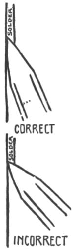
Fig. 19.
Remember: That the copper must be hot enough to make the solder glisten.
That a red-hot copper will not pick up solder.
That a red-hot copper burns away the flux, and that it destroys the tinning at the point of the copper; a red head also oxidizes the solder, making it brittle and weak.
That solder will not fill up a gap in a joint unless in very expert hands; joints should fit closely.
That a good joint should appear smooth; look as if painted on. A smooth joint is produced by a hot copper, clean metal, and good flux, but most of all, by leaving the copper long enough in the joint to heat it thoroughly.
That small joints are heated and soldered almost instantly.
That large joints require a longer time to heat up and that very heavy work requires a large copper and sometimes an outside source of heat as well—but we have nothing to do with such work in this book.
That work must be held together until the solder sets or turns gray, as it may spring apart while the solder is molten.
These are all very simple facts and should not be difficult to remember.
To continue with the practice piece: As soon as the solder has run in and around one end of the practice joint, remove the copper and solder the joint at the other end of the piece. As these joints are small, they should heat up and solder very quickly. One heating of the copper should do for[78] both joints, but be sure that the copper is hot enough before you try the second joint.
If difficulty is experienced in making your first joint and it does not stick together, apply more flux and try again.
The handle may be soldered to the biscuit cutter in the same manner after the practice piece is successfully completed.
Another Method of Applying Solder.—Sometimes bits of solder may be cut from the strip of wire solder and placed in the joint to be soldered. The hot soldering copper is then used to melt the solder into the joint. The joint must be well fluxed before the solder is placed in position.
The end of a strip of wire solder is sometimes held against the point of a hot copper as it is moved along a joint to be soldered. The solder is fed against the point of the hot copper as it melts into the joint.
Both of the above methods will be found advantageous when a gaping joint is to be filled with solder and it is desirable to apply a quantity of solder in one place.
THE PINE TREE DESIGN—CUTTING NARROW STRIPS OF TIN—BENDING TO SHAPE OVER DESIGN—SOLDERING COOKY CUTTERS—THE HANDLE
Cooky cutters of any simple design may easily be made from strips and pieces of tin cut from cans. They may be made to stamp out any simple design from the cake dough, such as flowers, leaves, trees, animals, boats, various insignia, etc.
When making the design for a cooky cutter, remember that raisins, currants, pieces of citron, nuts, etc., may be added to the cookies after stamping them out and used to accentuate the design, as eyes of animals, fruit on trees, etc.
First draw the design on paper exactly the same size you wish the cooky to be and be sure to use a very simple outline, taking care not to introduce too many intricate bends and to remember that a strip of tin must be bent to follow the outline of the drawing. Also remember that cake dough is not of very tough material and will easily break if cut in too narrow a strip in any place or part of the design.
Do not try to make too realistic a design but rather one that suggests the desired object. The pine or Christmas tree design is a very simple one to make.
The Pine Tree Design.—First draw the pine tree on paper, taking care to have both sides of the tree alike, Fig. 20. A very simple method of obtaining this result is to fold the paper exactly in half, open the paper out flat again and draw one-half of the tree, using the folded line as the center of the tree and using a soft pencil to draw with. Fold the paper together again using the same fold line, place the folded paper on a hard surface and rub the paper over the drawing with the bowl of a spoon so that the design is transferred to the other half of the paper, so that when the paper is unfolded the design will be completed and both sides of the design will be alike.
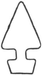
Fig. 20.
Cutting Narrow Strips of Tin.—When you have a satisfactory design drawn, cut open a large can so that when the tin from the can is flattened out you may cut from it a strip long enough to bend around and conform to your design and have only one joint. Be sure to trim up one edge of the tin to a straight line before starting to mark off a strip ½ inch in width, using the dividers for the marking operation as shown in Chapter II, page 35. Be sure to cut your strip as straight as possible and of exactly the same width for its entire length.
Bending to Shape Over Design.—When the strip is cut, bring the ends of the strip together and press the bend in to form an angle. This angle will not only form the top of the tree but will mark the center of the strip as well. Bend the strip apart until it conforms to the design on paper from the top of the tree to the first bend on one side as shown in Fig. 21. Mark the strip of tin at A. A.
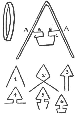
Fig. 21.
Take the flat-nosed pliers and bend the tin in on[82] each side to conform to the line B. Let the ends of the strip go past each other as shown in Fig. 21, 2, and in the illustration of bending. Next bend both ends of the strip at C. C. and so on until the complete outline of the tree drawn on paper is followed by the strip of tin. The various steps in the bending are shown in Fig. 21, 1 to 6. The joint at the bottom of the design should overlap about ¼ inch.
This joint may be held together with the flat-nosed pliers and soldered. Take care to have the ends that are to be soldered square with the rest of the design so that when the cutting strip is placed flat down on the cutting board all the cutting edges will touch evenly and cut well.
When you have the ends of the cutting strip soldered together, cut out a rectangular piece of tin somewhat larger than the design, at least ¼ inch larger in every direction. See that this piece of tin is perfectly flat and free from wrinkles.
Look carefully at the cutting strip and see that it conforms closely to the design and then lay it in the center of the rectangular piece of tin.
Secure a thin piece of wood slightly larger than the design. Wood from a packing box will do.
This strip of wood is held in place on top of the cutting strip in order to hold it when soldering the strip to keep it perfectly flat, and to prevent burning the fingers. The cutting strip gets very hot when it is being soldered in place.
Soldering Cooky Cutters Together.—See that your soldering copper is well heated and tinned; apply soldering paste to the entire joint where the cutting strip rests on the flat piece of tin and then apply the solder carefully in the usual manner with the hot soldering copper.
It will be found comparatively easy to apply solder to the longer parts of the strip, such as those forming the sides of the tree, but do not attempt to solder in the narrow crevice or crevices formed between the tree foliage, the trunk, and the top. Solder only where it is easy to introduce the point of the soldering copper, then apply solder inside that part of the design forming the tree trunk as illustrated in Fig. 23 by the dark lines.
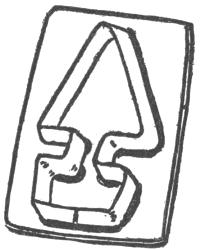
Fig. 22.
The cutting strip need not be soldered to the flat piece of tin forming the back in every small crevice that is not convenient to the soldering copper. But it must be soldered in such a way as to prevent the cutting strip from bending out of shape when used for cutting. So, if you may not solder it outside, solder it inside.
Be sure and hold the cutting strip firmly down to the flat tin with a flat piece of wood when soldering. If the soldering does not go along well, stop[84] and read over Chapters IV and V on soldering. Take plenty of time and make a good job of it.
When the cutting strip is firmly soldered to the tin, trim away the edges until they appear as shown in Plate VIII. Do not try to follow every indentation in the design but cut to the general smooth shape indicated which leaves no sharp corners. The edges of the tin forming the back of the cutter may be smoothed over with a small piece of fine emery cloth or fine sand-paper. Rubbing the edges gently with the emery cloth will dull them so that they are less apt to cut the fingers. This applies only to the flat piece of tin forming the back or top of the cutter, for the edges of the cutting strip should be left sharp.
Punch two or more holes through the back of the cooky cutter to form air vents as you did when making the biscuit cutter.
The Handle.—A handle may be made for the cooky cutter in exactly the same way as the handle made for the biscuit cutter. A strip of tin 1¼ inches wide and 4 inches long, is about the right size for the handle. The edges are folded in and the strip is rounded over an anvil and soldered into place as indicated in the photograph.
The edges of the handle should rest directly over the cutting strip under it.
When finished, the cooky cutter should be boiled up in the lye bath or washed with hot water and strong soap and then it is ready for use.
PLATE VIII
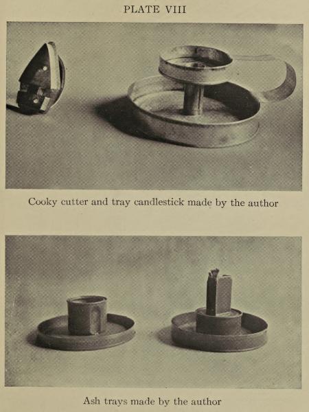
Cooky cutter and tray candlestick made by the author
Ash trays made by the author
TURNING OVER EDGES ON ROUND TRAYS—USING THE FORMING MALLET—MAKING AN ASH TRAY AND MATCH BOX HOLDER
Various round trays may be made from tin cans. These are very simple to make and are very attractive and convenient for ash trays, bottle casters and the like. A match box holder may be soldered to the center of the tray and any smoker will appreciate this. These simple trays have proved to be one of the most popular problems for certain wounded soldiers in an American base hospital in France.
Turning Over Edges on Round Trays.—Select a rather large can to cut down for a tray. A can from 4 to 6 inches in diameter is best with which to start tray making. This can should be round, as the square cans are very difficult, if not impossible, to handle when turning over an edge.
Set the dividers to 1¼ inches and scribe a line parallel to the bottom of the can. Cut the can down and be careful to cut it off as straight as possible at the scribed line.
Place a square maple block in the vise; the same maple block you have used for turning the edges of the handle for the biscuit cutter. Be sure that the edges of the block are square and sharp.
Set the dividers to ¼ inch, rest one leg of the dividers on the rim of the tray and scribe a line around the inside, ¼ inch down from the edge, as indicated in Fig. 23.
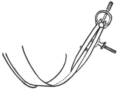
Fig. 23.
Rest the edge of the tray on the edge of the wooden block so that the line scribed ¼ inch down from the edge rests directly over the edge of the block as indicated in Fig. 24 a.
Tilt the tray back on the block until the edge is raised about ⅟₁₆ inch up from the surface of the[87] block, the line still resting directly over the edge of the block.
Using the Forming Mallet.—Take up the special forming mallet and use the rounded end to start hammering the tin down to the block, still keeping the tray tilted as indicated in Fig. 24 b. Turn the tray around as you hammer so that the tray is slightly flanged out by the mallet blows as you turn it around on the block.
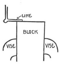
Fig. 24a.
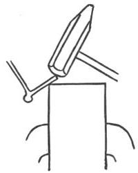
Fig. 24b.
Be sure to hammer the tin very gently and evenly, taking care not to stretch it down more in one place than another. Tin will stand considerable stretching if handled gently and evenly, but heavy mallet blows will stretch and crack it, and it will tear if unevenly stretched.
Never raise the edge of the tray away from the block more than ⅟₁₆ of an inch, but always tilt the tray back a little more each time you hammer entirely around it. The tin will quickly flange out and after having hammered entirely around the tray three or four times, the rim should flange out to about the angle indicated in Fig. 25, No. III.
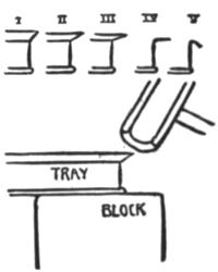
Fig. 25.
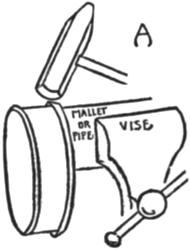
Fig. 26.
Try to hammer in such a way as to flange the tin over evenly from the scribed line. The mallet blows should be directed in toward the line which always rests at the edge of the block, rather than toward the edge of the tin.
When the edge has been turned over as far as[89] indicated in Fig. 25, No. III, change the position of the tray and rest the bottom of it on the top of the block and hammer gently on the edge as indicated in Fig. 25 until the edge or flange stands out at right angles to the side of the tray. Continue hammering until the edge of the tray stands at about the angle indicated in Fig. 25, No. V.
Remove the maple block from the vise and secure a round wooden mallet in it, the mallet being about 2½ or 3 inches in diameter, or a piece of iron pipe, if held in the vise, may be used for an anvil instead of the mallet.
Hang the tray over the end of the mallet or pipe and hold it firmly in position, turning it slowly around the anvil as the edge is hammered down to the side of the tray, Fig. 26.
Do not try to hammer the edge down all at once, but go entirely around the turned flange or edge several times with the mallet, hammering very lightly and bending the edge down more each time the tray is hammered around. The flanges or turned part will wrinkle slightly during the turning, but if the edge has been turned evenly and slowly from the start, this wrinkling will not matter, as the wrinkles will gradually hammer out. Try to hammer in such a way that the edge or top of the tray will remain rounded and not get hammered together (Fig. 27).
When the edge is turned completely in and touches the sides, reverse the forming mallet and use the wedge-shaped end to hammer the wrinkles out, taking care to hammer inside the edge so as not to flatten the edge of the tray, Fig. 28. The edge should look like Fig. 27, and then your tray is finished and ready to be boiled up in the lye solution and painted.
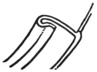
Fig. 27.
The edges of the tray may be made of any height that suits the maker, but never try to turn over less than ¼ inch at the edge nor any more than ⅜ inch, as either operation is very difficult, if not impossible.
The tin is taken up considerably in the turning and the ¼ inch marked off for the turned edge of the tray described above will be about ³⁄₁₆ of an inch when turned.
This turning operation is used a great deal for finishing the edges of different cylindrical and curved surfaces used in the tin can work, as a sharp thin edge should never be left about the work.
Making an Ash Tray and Match Box Holder.—Make a tray about 6 inches in diameter and ¾ of an inch in height when the edge is turned over, and then find a smaller can about 2½ inches in diameter,[91] such as a soup or baking powder can. Scribe a line around this can 1 inch from the base. Cut the can down to this line and place the can bottom up in the center of the bottom of the first tray, holding it in position with a stick of wood and soldering it to the tray.
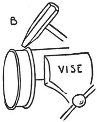
Fig. 28.
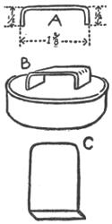
Fig. 29.
Open a box of safety matches and measure the diameter of the end of the box part that holds the matches. The usual measurement of the end of the inside box is ⅝ by 1⅜ inches.
Cut a strip of tin ⅝ of an inch wide and 2⅛ inches long. Make a mark ½ inch from each end of the strip and bend the tin at right angles at each end, using each mark for the bend.
The strip should then appear as shown in Fig. 29, A. Solder this strip in the center of the small can as shown in Fig. 29, B, but make sure that the cover of the match box will slide over it before soldering it fast.
Cut two pieces of tin 1½ inches wide and 2½ inches in length. See that they are cut perfectly square. Mark off a line ¼ inch in from one end of each piece and turn the tin at right angles from this mark to the edge.
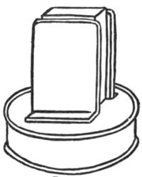
Fig. 30.
The corners at the opposite ends of each piece should be rounded off by cutting with the shears as shown in Fig. 29, C. Round over the edges with some fine emery cloth. Place the cover of the match box in position over the strip of tin soldered to the can in the center of the tray. Place the two pieces of tin against the two opposite sides of the match box as shown in Fig. 29. Then move them slightly away from the box and mark the position of the flanged ends where they rest on the can, remove the box cover and solder these pieces of tin in place.[93] Be sure to solder these pieces in such a way that the match box cover will slip between them easily and fit over the bent strip of tin at the bottom. The ash tray and match box holder will then be completed and ready for the lye bath and painting.
An extra coat of some high-grade spar varnish should be given the ash trays to prevent the hot ashes from burning the paint. This varnish should only be applied after the first coat or coats of paint are thoroughly dry.
The height of the trays at the edge may be altered to suit and also the height and shape of the can soldered to the center of the tray. The measurements are merely given for convenience in working out these first problems. Every effort should be made to think out problems of your own, taking the suggestions from the shapes of the cans themselves. Thus a square can may be soldered in the center of the tray, and small semi-cylindrical troughs of tin may be soldered to the rim of the tray to hold lighted cigars and cigarettes.
THE CANDLE SOCKET—CUTTING A HOLE IN THE DRIP CUP—MAKING THE HANDLE
After the ash tray and match box holder is successfully completed the next problem that should be taken up is the tray candlestick, a photograph of which is shown on the opposite page. This problem presents some interesting and instructive forming and soldering operations and should be made before attempting to make the toy auto truck.
Two trays should first be made up—one to be used for the base of the candlestick and one for the drip cup. The edges of both trays should be turned over carefully.
The Candle Socket.—The next thing to be made is the candle socket which is also used to connect both trays. Cut a piece of tin 2¾ by 3½ inches, set the dividers to ¼ inch and scribe a line ¼ inch inside three edges of the piece as shown in Fig. 31, No. 1. Clip off the corners and fold down the strip marked A, flat against the tin. C and B should be partially folded over but not closed up, Fig. 31, No. 2. These two flaps, C and B are to be locked together to form a locked seam as shown in No. 3.
If this seam or joint were merely lapped and soldered together the candle socket would melt apart if the candle should be allowed to burn down inside it.
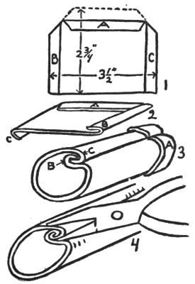
Fig. 31.
Place a small bar of iron in the vise jaws—this bar or pipe should be about ¾ inch in diameter and is used as an anvil over which to round up the candle socket.
Lay the piece of tin that is to be used for the candle socket over the anvil with the fold A[96] uppermost—bend the tin around the anvil with the hand or with light mallet blows, taking care not to close up the flaps B and C as you round the piece over the anvil. You will not be able to get the socket into a perfect cylindrical shape at first and until B and C are fitted together as shown in No. 3. Simply round the piece up as best you can until flap B fits into flap C. Then use a pair of flat-nosed pliers to pinch B and C together as shown in No. 4.
When the two seams are fitted together or locked the socket should be again placed on the bar and the hammering continued until the socket is cylindrical and the seam hammered together.
Examine a tin can—most of them have locked seams at the side.
If carefully made, this socket should fit a common candle which is ⅞ of an inch in diameter.
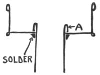
Fig. 32.
Cutting a Hole in the Drip Cup.—When the candle socket is completed, a hole should be cut for it through the bottom of the drip cup. The socket is slipped through this hole until the bottom of the flange A rests against the bottom of the drip cup, see Fig. 32. A small chisel should be used to cut the hole through the bottom of the drip cup. The[97] drip cup is rested on a small block of wood which is held in the vise jaws, and the chisel used in the same manner as a punch, the end of the wooden block supporting the tin as the chisel cuts through it. The cutting edge of the chisel should be about ⅛-inch wide and should be very sharp. Such a chisel may be purchased at most tool dealers or a ⅛-inch nail-set may be purchased and the end ground to a chisel point on a grindstone. A common steel nail may be used for a chisel if the point is filed off entirely and the end of the nail filed to a chisel point. The shank of the nail should be ⅛ inch in diameter.
Set the bottom edge of the candle socket in the center of the drip cup and trace a line around it with a sharp pencil or a steel scriber. Then place the drip cup on a block of wood and cut out the disk of tin inside the line, using a series of chisel cuts to follow the line. Take care not to cut the hole too large—it should just fit the candle socket as shown in the sectional drawing, Fig. 32. A half-round file may be used to file away any rough or jagged edges left by the chisel cutting.
Making the Handle.—A handle should next be made from a piece of tin 1½ by 8 inches. The handle should be made tapering and a dimensioned drawing for this is shown in Fig. 33. When the tin is cut to the shape shown the dividers should be set to ³⁄₁₆ inch and a line scribed ³⁄₁₆ inch inside each side of the handle. The tin should be folded[98] over on these lines so that the sides of the handle will be nicely rounded and made stronger. Directions for making a straight fold will be found on page 50 and need not be repeated here as the operation is very simple.
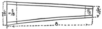
Fig. 33.
The handle should be shaped as shown in Fig. 34. It may be shaped or formed up by placing it over a round anvil and using a mallet in exactly the same way that the handle of the biscuit cutter was formed, see Fig. 35, except that the handle for the candlestick will have a better appearance if the folds are left on the outside, see Fig. 34.
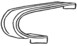
Fig. 34.
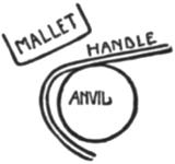
Fig. 35.
The ends of the handle should be bent over at right angles as shown in Fig. 34. The small end[99] hooks over the drip cup and the large end hooks over the edge of the tray or bottom of the candlestick.
The different parts of the candlestick are now ready to be soldered together. The socket should be fitted into the drip cup and these two soldered together first. Apply the solder to the bottom of the drip cup and socket in the angle where the socket and the drip cup meet, as shown in Fig. 32.
When the socket and the drip cup are soldered together they should be set in position in the center of the bottom tray and soldered in place. (The candlestick will have a much better appearance if the seams in the side of the drip cup, socket, and bottom tray are in line with each other when the candlestick is soldered together.)
The handle is the last thing to put in place and it is soldered to the drip cup and to the bottom tray—which will complete the candlestick.
Many pleasing varieties of this simple and practical candlestick may be made by changing the diameter and shape of the cans used for the trays and the length of the candle socket and the shape of the handle.
MAKING A PAIL FROM A TIN CAN—CUTTING AWAY THE SURPLUS TIN AT THE RIM—FORMING THE LUGS FOR THE HANDLE—RIVETING THE LUGS IN POSITION—FORMING A WIRE HANDLE
Riveting is one of the most useful operations connected with metal working of all kinds, and it is very frequently used in tin working where it is not advisable to join the metal with solder; or riveting may be employed in connection with a soldered joint to strengthen it and to prevent the joined pieces from melting off, such as the lugs or handle holders on a pail used for cooking, etc.
Riveting is a very simple operation. The rivets are usually made with a flat or rounded head attached to a short cylindrical shaft or shank. A hole is punched through each piece of metal to be joined. The pieces of metal are placed together so that the holes are in line and a rivet shank slipped through these holes. The head of the rivet is then rested on a flat iron or steel anvil and the headless end is hammered over until it forms into a second head and thus holds the two pieces of metal tightly together.
The pail offers a very simple problem in riveting[101] and it is very easy to make a substantial pail from a tin can.
Making a Pail.—Select a large, clean, round can for the pail. A one-gallon fruit or vegetable can makes up into a very useful pail. Use a can opener to cut away the remaining tin of the lid but take care not to mar the rim of the can. Rolled rim cans make the best pails.
When the lid is cut away a jagged edge usually remains near the rim and this must be trimmed away and the remaining tin hammered down close to the rim. If more than ¼ inch of the tin of the can lid remains next to the rim of the can it should be trimmed away with the metal shears until a strip of tin remains next to the rim about ¼ inch wide.
Cutting Away Surplus Tin at the Rim.—(A pair of curved metal shears are very useful for making circular cuts of this nature if you have them, but the surplus tin may be trimmed away with the straight shears if small cuts are taken with them.) Cut into the tin next to the rim with the shears—the cut should be made at right angles to the rim and extend in to the rim. Now take a pair of strong flat-nosed pliers and grasp the tin firmly with them to the right of the cut and with a quick downward motion of the plier jaws start to break away the tin next to the rim as shown in Fig. 36. The tin will break away at the angle of the lid and the rim and should peel away easily with a series of quick downward[102] movements of the plier jaws—a fresh grip should be taken for each downward movement of the plier jaws and the ends of the plier jaws should be pushed up against the rim each time that they are moved into a new position.
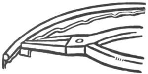
Fig. 36.
When the tin is trimmed away place the rim of the can on the end of the maple block and use the rounded end of the forming mallet to hammer the tin down tight to the rim, see Fig. 37. The pail is then ready for the lugs or handle-holding pieces at the sides. These are to be soldered and riveted in place.
Forming the Lugs for the Handle.—Cut two pieces of tin, each 1½ by 3½ inches, fold over ¼ inch on each of the long sides of these two pieces, then double over each piece with the folds outside, as shown in Fig. 38. Snip off the corners, then place the lugs on the maple block and punch three holes in about the position shown. See that the[103] holes are slightly larger than the shanks of the rivets to be used, but do not get the holes very much larger than the rivets.
Rivets are supplied by the hardware stores in plain soft black iron and also tinned. The tinned rivets are best for tin work as they may be easily soldered to the work if necessary. These tinned rivets are used for representing faucets, try-cocks, etc., in making tin can toys. Several dozen or a box of No. 14 Tinned Rivets should be purchased.
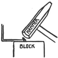
Fig. 37.
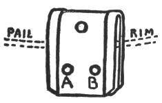
Fig. 38.
Riveting the Lugs in Position.—Solder the two lugs in position on each side of the top of the pail. These two holes should come below the rim.
Place the pail over a round log of wood held in the vise and punch the holes A, B through the tin of the pail, using the holes previously punched in the lugs of the pail as a guide.
Remove the log of wood from the vise and place[104] a large piece of round pipe in it for an anvil on which to rivet. Push a rivet through the hole A, and place the pail on the pipe in such a manner that the head of the rivet rests on the iron pipe. Take a small riveting hammer or a small machine hammer and hammer down the small end of the rivet that projects above the work, see Figs. 39 and 40. Hammer rather gently using many light quick blows instead of a few smashing heavy ones. The light blows tend to form a better head on the rivet and to hold the metal more securely in place.
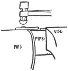
Fig. 39.
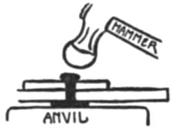
Fig. 40.
After you have had some experience in riveting, you will find that the ball peen, or rounded end of a machine hammer, is better to rivet with than a flat-ended hammer.
When two rivets are placed in each of the lugs the pail is ready for the handle.
Forming a Wire Handle.—Pail handles may be made of ⅛-inch galvanized wire or any piece of strong, stiff wire that is handy. The galvanized wire is best as it will not rust.
Cut a piece of wire 14 inches in length. Do not try to cut this wire with your metal snips but use a heavy pair of wire-cutting pliers if you have them. A simple method of cutting wire is to place the wire in the vise and use the corner of a file to cut through it.
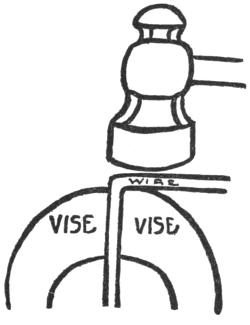
Fig. 41.
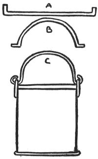
Fig. 42.
Trying to cut heavy wire with the metal shears will ruin them; besides, you can’t do it.
Mark off 1¾ inches from each end of the piece[106] of wire you have cut for the handle and bend each end down at right angles from this mark, see Fig. 42, A.
This may be easily done by placing the wire in the vise so that the mark for bending is held exactly at the top of the vise jaws, then use a hammer to bend the wire over at right angles, see Fig. 41.
Place the wire over the pipe held in the vise and use a wooden mallet to round it over to the form shown in Fig. 42, B. Slip the ends of the wire handle through the holes punched for it in the lugs on the pail and then turn the wire up at the ends with a heavy pair of pliers until it looks as shown in Fig. 42, C, and the pail is completed.
If the pail described above is made of a rolled-rim can it may be safely used for camp cooking, as there is no danger that it will melt apart over the fire. When a spout and a lid are added to the pail, it will serve as an excellent coffee pot. A coffee pot and other cooking utensils are shown in Fig. 95.
THE WHEELS—FOUR WAYS OF MAKING WHEELS OF TIN CANS—MAKING A WHEEL FROM A CAN WITH SOLDERED ENDS—MAKING WHEELS FROM ROLLED-RIM CANS—TWO TYPES OF WHEELS MADE FROM CAN LIDS
A very simple and strong toy automobile truck may be made of tin cans. If the foregoing problems have been carefully worked out, there is no reason why one should find the truck difficult to make, provided the directions are carefully followed.
As the construction of a truck is typical of so many wheeled toys, it was selected as the best type with which to begin. Various fittings may be added, such as lights, fenders, running boards, handles, tool boxes, etc., but only after the plain truck chassis, hood, seat and wheels have been successfully assembled. This first real problem in toy making should be kept as simple as possible.
Wheels form the most important part of any rolling toy, so these will be taken up first and each method of making them discussed at length.
Four Ways of Making Wheels of Tin Cans.—Both types of tin cans may be used for making[108] wheels, the rolled rim and the soldered flange can, but the method of making the wheel is different for each type of can. The press-in can lids from molasses and syrup cans may also be used for making wheels.
Making a Wheel from a Can with Soldered Ends.—Suitable truck wheels may be made from the smallest size evaporated milk cans. Condensed milk cans are too large for a small truck, though either of the above mentioned cans have the soldered flanged ends.
The contents of these evaporated milk cans is usually poured through one of two holes punched through the cover. This renders the cover practically useless for making one side of the wheel, unless the holes are small, so that eight cans will have to be used for making four wheels.
If the cans are opened on the side with a can opener but four cans need be used, as each end of the can is then intact. These wheels are made by removing one lid from the can, cutting the can down to the required wheel width, and then soldering on the lid again. When the ends of the can are intact, the can is cut in two parts by cutting around the sides of the can with the can opener. One part of the can is cut down to the required height as in making a tray; this height represents the width of the wheel. The end is melted off the other part of the can and this end is placed over the first part of the[109] can that is cut to the width of the wheel. It is then soldered in place and the wheel is made.
If plenty of evaporated milk cans are not handy, it is better to buy four new, filled cans from the grocer, as these small cans cost only eight cents when filled with milk.
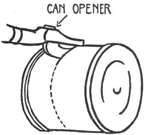
Fig. 43.
Empty the cans by cutting a slit in the side with a sharp can opener, see Fig. 43. Hold the cans over a glass or jar until the milk runs out into the glass, then rinse the cans out with hot water which will also remove the label. Continue cutting around the can with the can opener until it is completely cut in half. All four cans should be emptied and cut in two[110] in this manner. As for the milk, any cook will know what to do with that.
Open the dividers to ⅜ inch and scribe a line around the bottom of one of the cans that has been cut in two, using the soldered edge of the rim against which to rest one point of the dividers, as shown in Fig. 44. Cut away the surplus tin exactly as if you were making a tray. If the cans have become dented when they were being cut with the can opener, place them on a round anvil and remove the dents by hammering gently with a mallet.
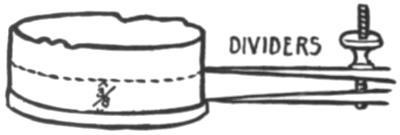
Fig. 44.
Take up another half can and make a cut from the edge down to the flange at the bottom as shown in Fig. 45. Take an old pair of flat-nosed pliers and hold it over an open flame, such as a gas range or the flame of a soldering copper heater, until the solder shows in a bright line at the joint of the can and lid, then take the forming mallet and give the lid at the bottom a sharp tap or two with it which should knock the lid away from the sides of the can held by the pliers, see Fig. 45. Do not use your good pliers to hold the can over the flame, as the[111] heat will soon take the temper out of them and render them useless.
It is not necessary to get the can red hot in order to melt the solder.
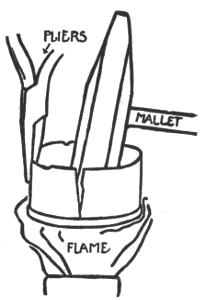
Fig. 45.
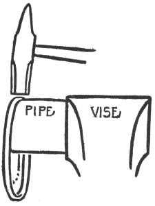
Fig. 46.
When the lid is removed, try to fit it on the other part of the can and it will be found impossible to force the tin into the lid without denting the sides of the can. The rim or flange at the edge of the lid must be enlarged in order to place the lid back on the can. The edge of the sides of the can to be fitted into the lid should be filed with a small flat file to remove the tin raised by the metal shears when cutting around the can.
To enlarge the rim of the lid, place it over a piece of pipe held in a vise and hammer the rim with a light hammer, turning the lid slowly around on the anvil as you hammer, see Fig. 46. After hammering completely around the flange once or twice, try to fit the lid to the can again. It should fit without much hammering. Squeeze the lid on the can and hammer it gently into place, the wheel being placed flat on the bench at the time. Solder the lid in place and the wheel is finished except for the axle holes.
A small drop of solder will be found on the lid of all evaporated milk cans. Melt this away with a hot soldering copper and a round hole will be found exactly in the center of the lid. This hole may be enlarged to fit the wire used for the axle.
Find the center of the side of the wheel with the dividers as described on page 37, Chapter II.
Use an ice pick to punch a tiny hole exactly in the center of the wheel. If ⅛-inch galvanized wire is to be used for an axle, push the ice pick further into the hole, turning the pick while doing so, until the hole is just large enough to fit the axle wire. Repeat the process on the other side of the wheel until the hole there is enlarged to fit the axle wire, Fig. 47.
If the axle holes are not exactly in the center of the wheel, it will not run true. A little care used in[113] punching the holes will cause it to run true enough for any toy.
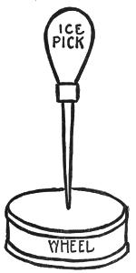
Fig. 47.
If you possess a hand drill and a drill the same size of the wire used for an axle, you may drill the hole in the center of the wheel instead of punching it through. To do this, first find the center of the wheel and then make a slight dent exactly in the[114] center of the wheel with the ice pick or a small center punch. The point of the drill is placed in this dent when starting to drill the hole. I find it better to use a ⅟₁₆-inch drill and drill a hole through the center of the wheel with this first, then use a drill the same size as the axle wire and enlarge the ⅟₁₆-inch hole with this.
In any case, the wheel should be soldered together before the holes are put through the centers. Finish up the four wheels and lay them aside until the truck is nearly completed, as the wheels are the last things to be added.
Galvanized wire of ⅛ or ³⁄₁₆ inch diameter is usually used for axles. This wire is usually carried in stock at hardware stores. It is usually furnished in coiled form and must be straightened out before being used. A piece is cut from the coil of wire long enough to make the two axles. It should then be placed on a flat metal surface and hammered straight.
Making Wheels from Rolled-Rim Cans.—A very strong wheel may be used from rolled-rim cans. This process is slightly different from that used with the soldered flange cans. Wheels from 2½ to 6 inches in diameter may be made by this second method, but unless this type of wheel is made from very small cans it is not so suitable for the truck as the wheels made from small evaporated milk cans.
Eight rolled-rim cans will have to be used to make four wheels unless the cans are opened at the side when first emptied. Both types of wheels should be made so as to become familiar with the making of each type, as both types are used in making the models shown in this book.
This second type of wheel is rather easier to make than the first, but you should know how to make either type, as then many different sizes of wheels may be made with whatever cans you may have. The rolled rim is more often employed in making large cans than in the smaller ones.
To make wheels suitable for a truck of the size described here, small soup cans may be used; these are usually rolled-rim cans.
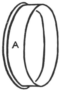
Fig. 48.
To make a wheel from two rolled-rim cans, a line should be scribed about the base of the can, ⅜ inch from the bottom, and the can cut down to this line, see Fig. 48, A. Scribe a line ¼ inch from the base of the second can and cut this can down to this line. Make a cut every ¼ inch around the tin at the[116] side of this second can, each cut to reach the base or rim of the can, see Fig. 49, B.
Place this part of the wheel on the wooden block and use the riveting hammer (C) to drive the cut side of the can inward as shown in Fig. 49, B.
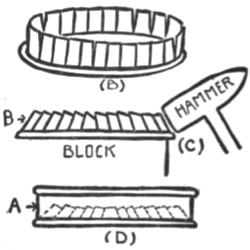
Fig. 49.
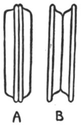
Fig. 50.
Now take up the can cut down to ⅜ inch and place it over a pipe anvil which is held in the vise. Use a metal hammer and hammer around the edge of this can two or three times to enlarge it. Turn the can around the anvil when hammering it. Then try to push it down over the second or turned part of the second can as shown in Fig. 49, D. If it does not fit, continue the hammering until the two parts of the wheel fit together and then solder them in place and the wheel is completed, except for the[117] axle holes, which may be put in exactly the same way as they are put in the first type of wheel.
PLATE IX
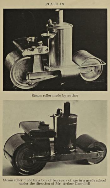
Steam roller made by author
Steam roller made by a boy of ten years of age in a grade school under the direction of Mr. Arthur Campbell
The large roller of the toy steam roller shown in Plate IX is made of rolled-rim cans as are the large wheels of the toy traction engine shown in Plate XVIII.
Be sure to try both methods until you understand them thoroughly, as a great deal depends on the ability to make good wheels for a toy model.
Two Types of Wheels Made from Can Lids.—A third method of making wheels is to use two can lids soldered together, but as it takes quite a while to collect eight can lids of the same diameter, it is better to employ this method only occasionally, as for flanged car wheels made to run on a track, etc. A glance at Fig. 50, A, should be enough to show how these wheels are made up of two pushed-in can lids soldered together at their largest diameter.
The first two methods described result in wheels that look like the heavy truck wheels employed on actual trucks.
Another type of wheel may be built of the flanged pushed-in lids. In this type the lids are soldered together in just the opposite way as that described in the third method, so that the flanges are on the outside of the wheels. These wheels are generally used for belt wheels on the mechanical models, Fig. 50, B.
FORMING THE CHASSIS—USING THE WOODEN ROOFING FOLDER—FOLDING—USING THE VISE FOR SHORT FOLDING—USING THE HATCHET STAKE FOR FOLDING
Forming the Chassis.—The chassis or frame of the truck may be made from a single piece of tin cut from a gallon fruit can. All four edges are turned down so as to form a shallow tray or box.
Cut a piece of tin 12¾ by 4¼ inches. Use the dividers to mark off a line ⅜ of an inch inside all four sides, but be sure that the tin is cut perfectly square before you do this inside marking. Cut in to the lines A A on all four of the darkened lines as shown in Fig. 51, A.
Place the tin on a sharp-edged block and fold down the long sides 1 and 2 first. Remember not to try to fold these long sides or folds down all at once, but rather go over them two or three times lightly with the mallet as they are being turned down at a right angle. Take care that the tin folds over exactly at the line.
When the sides 1 and 2 are folded down at right angles, fold down the ends 3 and 4. This will leave[119] four small ends of the two long sides projecting beyond the ends as shown in Fig. 51, B. Fold these in over the ends of the chassis with a mallet. Hold them in place with a pair of flat-nosed pliers and solder them to the ends where they touch, so that the chassis appears as shown in Fig. 51, C.
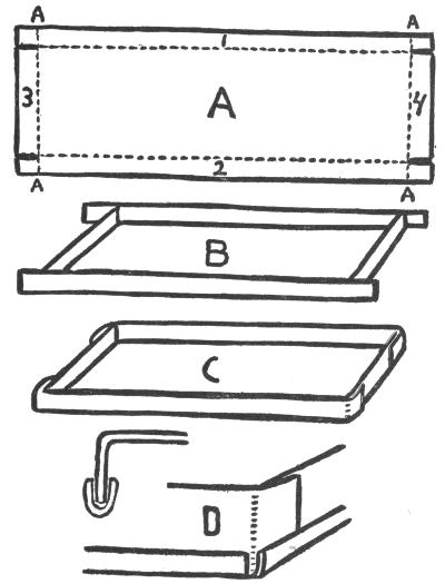
Fig. 51.
Using the Wooden Roofing Folder.—Folds of all kinds may be very easily and quickly made by using the wooden roofing folder, Plate XII. The work turned out by this simple machine is very straight and true, particularly long folds or angles of tin. The gauge may be set at any desired width up to ⁷⁄₁₆ of an inch and any number of folds of the desired width can be quickly and accurately produced by inserting the tin between the holding bars and closing up the folder.
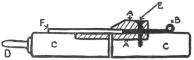
Fig. 52.
The holding bars are shown at A A, Fig. 52. The adjustable gauge at B, C C are the wooden supports which are hinged together. D is the iron handle, E the adjusting screw, F is the piece of tin to be folded.
PLATE X
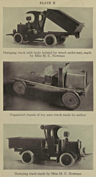
Dumping truck with body hoisted by winch under seat, made by Miss M. C. Newman
Unpainted chassis of toy auto truck made by author
Dumping truck made by Miss M. C. Newman
PLATE XI
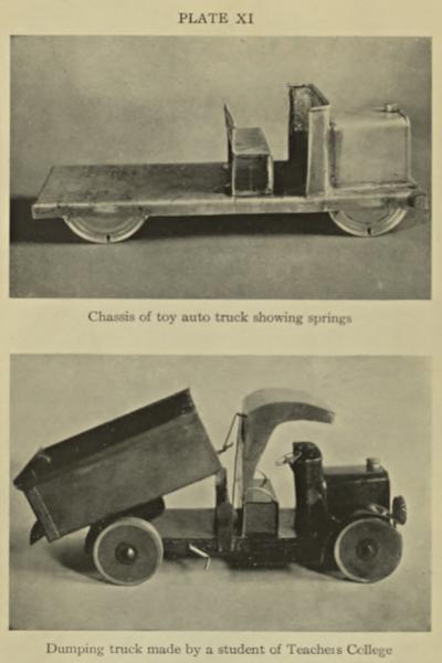
Chassis of toy auto truck showing springs
Dumping truck made by a student of Teachers College
PLATE XII
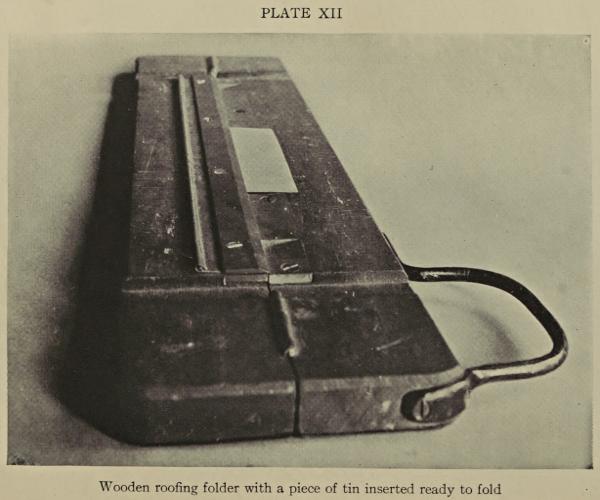
Wooden roofing folder with a piece of tin inserted ready to fold
The folder is shown in Fig. 53. Both of these views are sectional to show the working of the folder. The actual construction may be easily understood by looking at the actual folder. The gauge B, Fig. 52, is adjusted by first loosening up the five screws E with a screw driver and then pulling in or pushing out the gauge B to the desired width of the[121] fold to be made. The screws E are then tightened up with the screw driver and the tin inserted between the pieces A A. The folder is then closed by grasping the handle D and closing the two sides of the folder together. When the folder is opened, the tin will be found to be folded over.
The fold may then be completed with the mallet if it is desired to close it up against the tin. To form a right angle the folder is not completely closed. A little experimenting with a piece of scrap tin will show how far to close the folder in order to obtain a given angle.
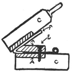
Fig. 53.
Care should be taken to set the gauge B parallel with the holding bar A. The folder is ordinarily set at ¼ inch. This is the width of most of the folds made in the tin. This simple machine will save much time in tin working and one should be purchased if possible. It is practically the only way a long fold in a narrow strip of tin may be made accurately.
The folder may be used to fold down the two long sides of the chassis, the ends may then be turned down over the edge of a block as the ends of the long folds will prevent placing the short folds in the folder. Narrow strips of tin may be folded over[122] and hammered together with the mallet. These strips of tin may be slipped over the sharp edges at the bottom of each side of the chassis, thus making the edges very strong and removing the danger of cutting the fingers. Fig. 51, D, shows an enlarged view of a corner of the chassis with the folded tin strips slipped over the lower edges.
These narrow folded strips are very easily made on the folding machine. Cut two strips of tin ½ by 12 inches and set the folder to fold ¼ inch, place the tin in the folder and fold it over. Remove it from the folder and hammer it nearly together with the mallet and then place a separate strip of tin in the folded part and continue hammering with the mallet until the folded tin is closed in on the inside or inserted strip of tin.
The folded strip is then ready to slip over the edge of the side of the chassis and to be soldered to it in several places; that is, the folded strip need not be soldered to the chassis continuously, but may be held in place by soldering about every four inches.
The two short strips of tin ½ by 4 inches should then be cut, folded and soldered in place at the short ends of the chassis. (No sharp edge should be left about a tin can toy when it may be avoided by folding or covering.)
A long narrow strip of tin is rather difficult to fold without the use of a folder, but it may be done with the mallet and block as follows:
Folding.—If a strip of tin ½ by 12 inches is to be folded over, it is better to cut a strip of tin 1¼ by 12 inches. Mark off ¼ inch all along one long edge and fold it down over a block as in making the handle of the cooky cutter, for you will then have more metal to hold to while folding. When the piece is completely folded down to a right angle, turn it over on the block and close the tin down with a mallet, inserting a piece of tin before closing the tin together. Then the surplus tin may be cut away and you have a narrow folded strip. As in all folding by hand using the mallet and the block, the tin should be gradually folded into place.
Using the Vise for Short Folding.—The vise may be used to fold short pieces of tin very accurately. The folding line is first marked on the tin; the tin is then placed and held in the vise jaws so that the line is parallel with and exactly at the top of the jaws. The mallet is then used to hammer the tin over to the required angle, see Fig. 54. A very sharp accurate fold should result.
Using the Hatchet Stake for Folding.—A special stake has been devised for folding tin. This is called the hatchet stake and is listed in the supplementary tool list. It is made in the shape of the letter T. The horizontal part is made like a long narrow-bladed hatchet, and the vertical shank attached to it may be held in the vise or set in a hole in the bench, see Fig. 55.
The top edge of this tool is perfectly straight and fairly sharp. One side of the blade runs straight down from the edge and the other side slopes down at an angle considerably less than a right angle. The top edge of the hatchet stake is used to fold the tin over and it is specially formed to permit the folding of more than a right angle.
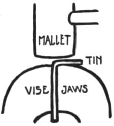
Fig. 54.
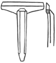
Fig. 55.
To use the hatchet stake, a folding line is first marked on the tin. This line is kept directly over and parallel with the top or edge of the stake and the mallet is used to fold the tin, the mallet blows being directed at the top of the stake as shown in Fig. 56.
The hatchet stake is a very handy tool about the shop, even if a folder is included in the equipment,[125] as there are some jobs that will not permit the use of the folder to complete them.
Strips of tin as long as the blade of the hatchet stake may be accurately folded over as follows:
A strip of maple 1 inch thick and 2 inches wide and as long as the blade of the stake may be clamped against the flat side of the blade of the hatchet stake with the tin to be folded held tightly between the maple strip and the blade. The mallet is then used to fold the tin over toward the sloping side of the blade, Fig. 57. Sometimes two strips of maple may be clamped to a piece of tin to hold it accurately while being folded, but this method is rather cumbersome.
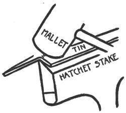
Fig. 56.
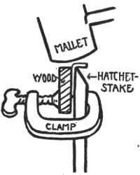
Fig. 57.
The different methods of folding have been described[126] at length so that the reader may become familiar with all of them, but a great deal of folding may be done over a sharp-edged maple block, if you have nothing else with which to work.
Professional tinners use a very convenient folding machine made of metal, but these are very costly and need not be described here.
MAKING THE HOOD AND RADIATOR—CUTTING THE VENTS—SOLDERING ON THE FILLER CAP
The hood and radiator may be made from a cocoa tin, a small olive oil or cooking oil can, provided that the can is shaped as shown in Fig. 58, which shows the bottom and sides of a cocoa tin.
The can is first cut down to the dotted line A. Then the can is cut at the dotted line B. Then some holes are punched in regular rows in the bottom of the can to produce the radiator. Slits are cut in the side of the can to form vents and a cap from a tooth-paste or paint tube is soldered on near the rolled rim for a filler cap and the hood is complete as shown in Fig. 59.
The rectangular can selected for the hood is marked and cut to shape as follows: Open the dividers to 2⅝ inches and mark the line A around the can, Fig. 58. Before cutting the can down to this line set the dividers to 2¼ inches and mark the line B horizontally around the can. To do this, rest the can flat on the bench and on the side that is to form the top of the hood. Rest one point of the dividers on the bench and let the other point rest[128] against the side of the can where the dotted line B is indicated. Still holding the can flat on the bench, move it against the divider point in such a manner that the line B is scribed horizontally around the sides and bottom of the can.
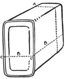
Fig. 58.
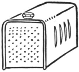
Fig. 59.
Cut the can down to the line A, then take up a small sharp-cornered file and file completely through the rolled rim at the corners marked C and C on the line B. Use the edge of the file and make a triangular cut. This filing will greatly simplify cutting the rolled rim which is hard to cut through with the shears.
Then cut into the rim on the line B, cutting from the line A. Bend the two halves of the can open far enough to admit the shears and cut across the bottom of the can on the dotted line B. Cut very[129] carefully so that the part of the can at the line B, forming the bottom of the hood, will rest flat on the bench all around. If it rests flat on the bench, it will rest flat on the tin frame of the truck where it is to be soldered in place.
The next thing to do is to punch the holes to form the radiator. The front of the hood is rested on a block of wood and a very sharp punch should be used for punching the holes, such as an ice pick or a very sharp-pointed nail.
First mark off the radiator in regular squares, using the depressed line usually found in the bottom of this type of can as a boundary line for the squares. Divide up the space into squares as indicated in Fig. 60, A, leaving a clear border of tin all around the space to be punched.
Find a block of wood that will fit inside the hood as shown in Fig. 60, C, and place one end of this in the vise. See that the end is sawn off square before placing the hood over it in the position shown.
Take up the punch and carefully punch the holes as they are marked by the dots in Fig. 60, A, at each line intersection. Then punch a hole in the center of each square and then a hole should be punched between every other hole on all the lines forming the squares, see Fig. 60, B.
Care should be taken to punch all the holes of the same size and to get them in regular rows. This makes a neat and workman-like job.
Cutting the Vents.—Vents may be cut in each side of the hood with a sharp chisel. An old wood or carpenter’s chisel about an inch wide will do very well or a sharp cold chisel may be used.
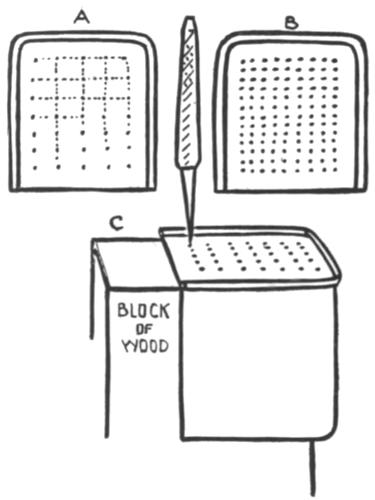
Fig. 60.
Use the same wooden block that you used to[131] punch out the radiator on and place it horizontally in the vise jaws so that enough of it projects beyond them to support the hood as shown in Fig. 61.
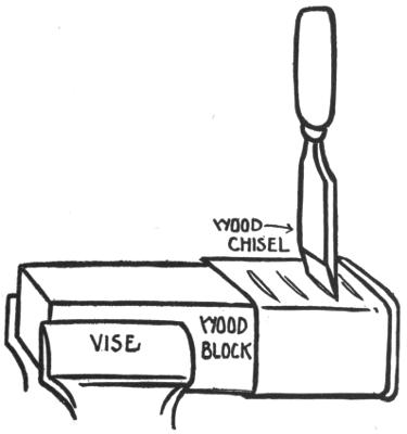
Fig. 61.
Use the dividers to mark off four or five vents and see to it that they are laid out square with the hood. Try to find a chisel that is as wide as the vent is long, a 1-inch cutting edge is about right. Place the edge of the chisel squarely on the mark[132] and hammer it through the tin with several blows from the mallet. Make these cuts very straight and parallel with each other. Cut the vents in both sides of the hood and the hood is then ready to have the filler cap soldered on.
Soldering on the Filler Cap.—Use a large sized screw cap of a tooth-paste tube or the cap from a paste or paint tube for the filler cap. Some of these caps are octagonal in shape and have various initials stamped on the top and these look very much like the filler caps used on the radiators of real automobiles.
Clean away all paste or paint from the inside of the cap and then scrape the lower edge bright and clean. These caps are usually made of a combination of metals that is very much like the solder used for soldering tin and they will melt very easily if brought in contact with a soldering copper, so that the cap must be soldered to the hood by an indirect heating method.
Soldering paste is first applied to the top of the hood where the cap is to be soldered and then a small puddle of solder is applied to the tin at this place with a hot soldering copper. The solder is allowed to cool and then the cap is placed in position on the solder after applying a bit of soldering paste to its lower edge.
Heat the soldering copper very hot and apply it inside the hood so that as much of the point as[133] possible rests directly under the puddle of solder on which the cap rests, Fig. 62.
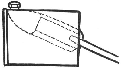
Fig. 62.
Hold it in this position until the puddle of solder melts and a bright line of solder is seen to run around the base of the cap where it rests on the hood. Remove the copper just as soon as the solder melts and runs around the cap and let the solder harden before moving the hood about. If the cap moves out of place while the solder is molten, owing to the bubbling of the soldering paste, it may immediately be pushed back into place with a matchstick before the solder hardens.
The hood will become very hot before the solder melts under the cap, but it may be easily held to the bench by wrapping a rag around it to protect the hand.
A thick square bar of iron may be heated to a dull red at the end and used in place of the soldering copper for soldering on the cap. Either the copper or the bar of iron must be very hot. They must be heated to a much greater temperature than ordinarily used for soldering.
When the filler cap is soldered in place the hood is ready to be soldered to the frame, but the dash-board and seat should be made before this is done.
THE DASH-BOARD—THE SEAT—ASSEMBLING THE TRUCK—SPRINGS—SOLDERING THE WHEELS ON THE AXLES—STRIP WASHERS
The Dash-Board.—The dash-board is the next thing to be made, and then the seat. The hood, dash-board and seat are then soldered to the frame. Four imitation springs are then made and soldered to the bottom of the frame; holes are punched in these for axles; the wheels and axles are put in place, and the chassis of the truck is finished.
The dash-board may be formed in two ways; one way is to use part of a rolled-rim can, the rolled rim forming the top, and the other way is to fold over three edges of a piece of tin and form this into a dash-board. The first method looks better, but the last method is easier.
Select a large rolled-rim can, measure off 5¼ inches along the rolled rim and from each end of this measurement, run a line 2¼ inches down the side of the can. Then mark a line around the can 2½ inches down from the rolled rim and cut the can down to this line exactly as you would cut a can down to any line, see Fig. 63.
Then cut out the piece 2½ by 5¼ inches including the rim. Use the flat-nosed pliers and break away the tin next the rim where the can was first opened with the can opener, just as you did when making a pail. Hammer down any tin left next the rim and then place the piece of tin on the bench or flat anvil and flatten it down, rolled rim and all.
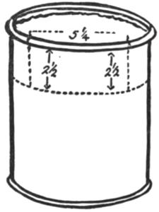
Fig. 63.
Use the dividers to mark off ¼ inch along the two short ends of the piece at right angles to the rim, then use a file to cut off ¼ inch at each end of the rolled rim. Cut in on each of the darkened lines A A to the lines B just under the rolled rim,[137] Fig. 64. Then fold the metal in between the lines B and C to give a rounded edge to the sides of the dash-board, as shown in Fig. 65.
Place a piece of round bar iron or a pipe about 1 inch in diameter in the vise and round over each end of the dash-board so that the folded edges are inside as shown in Fig. 65, and then round over the ends of the rolled rim with a flat file to make them smooth and the dash-board is finished.

Fig. 64.
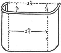
Fig. 65.
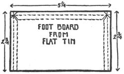
Fig. 66.
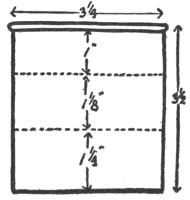
Fig. 67.
To make a dash-board out of a flat piece of tin, cut out a piece 2¾ by 5¼ inches. Set the dividers to ¼ inch and scribe a line ¼ inch inside three edges[138] of the piece. Cut off two corners at the top and fold in the flaps to the dotted line as shown in Fig. 66. Round over the ends of the dash-board as described above and to the same dimensions.
The Seat.—A very simple seat may be made for the truck out of three pieces of tin. Use a piece of tin with the rolled rim at the top as in making the dash-board. Cut a piece of tin 3¼ by 3½ inches, fold in two of the sides exactly as you did for the dash-board and cut off the rolled rim until it is even with the sides after turning and round over the ends of the rolled rim with a file.
Use the dividers to mark two lines parallel with the rolled rim, one line 1 inch in and the other 2⅛ inches as shown in Fig. 67 by the dotted lines. Bend the piece over a block as shown until it is shaped like the seat shown in Fig. 68.
Cut two pieces of tin 1⅜ by 1¼ inches. Mark a line ¼ inch in from the ends of one of the short sides of each piece and bend this part at right angles, Fig. 68, A. These two pieces are to be slipped under each end of the seat and soldered to it and then trimmed off with the shears until the whole bottom edge of the seat rests flat on the frame where it is to be soldered.
The two side pieces or supports are made too long purposely so that they may be trimmed off after they are soldered to the seat. The hood, dash-board and seat should be soldered in place.
Assembling the Truck.—Set the dividers to ¼ inch and scribe a line ¼ inch in from the front end of the frame. Place the front of the hood parallel with this line and see that the hood is set exactly in the middle of the frame; that it is set at the same distance from the side of the hood to the side of the frame on each side. Solder the hood in place.
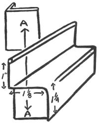
Fig. 68.
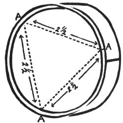
Fig. 69.
When soldering the hood to the frame, it is better to rest the frame on a block of wood so that the block supports the frame that is directly under the hood when soldering the hood to the frame.
The block will prevent the tin from bulging down from the heat of the copper and from the pressure of the hand when holding the hood in place to solder it.
Set the dash-board in place back of the hood and see that it fits snugly in place against the hood and also the frame and then solder it in place. If every joint is made to fit snugly before attempting to solder it, no trouble should be experienced, but sometimes a crack will develop owing to the expansion of the tin under heat of the soldering copper. These cracks may be filled in with solder by feeding a strip of solder against the point of the hot copper when soldering. This causes a lot of solder to run into the crack and fill it.
Solder the seat in position so that the front of the seat is about 1 inch from the ends of the dash-board.
Springs.—Holes may be punched through the sides of the frame and the axles run through them if a very simple truck is to be made, but imitation springs may be easily made from part of the sides and bottom of a can. These springs raise the frame of the truck above the axles and give it a more realistic appearance.
Cut two three-inch cans down to ⅜ inch in height. Turn these cans bottom up and place the ruler across the rim of each can bottom in turn in such a way as to measure 2½ inches from rim to rim. Then measure off another 2½ inches on each rim as shown in Fig. 69. File through the rims at A A and then cut straight down the sides of the can at A A A which should give you three springs from each can.
Solder two springs to the bottom and side of the frame ½ inch from the front end and the two rear springs should be soldered 1 inch in from the back end.
Use an ice pick to punch a hole in each spring to receive the axle and be sure that these holes are all the same distance from the top of the frame (use the dividers to determine this), and also that each hole is square across from the opposite axle hole (use the try square to determine this).
The axle holes should be punched through with an ice pick and be made somewhat larger than the axle wire so that the axle wire fits very loosely in the hole, but be sure to have all the holes the same size.
Soldering the Wheels on the Axles.—The wire axles should be cut long enough to go entirely through each wheel and across the frame and to allow a distance of ¼ inch between the frame of the truck and each wheel. The length of the axles may be easily determined by placing the frame of the truck flat on the bench and placing the two wheels in position, each wheel to stand out ¼ inch from the side of the truck. Measure the distance with a ruler from the outer edge of one wheel to the outer edge of the other and add ⅛ inch to this distance, see Fig. 70. Cut the two wire axles to this measurement and see that they are perfectly straight after cutting.
Place one end of an axle through a wheel until the end of it projects beyond the outside of the wheel about ⅟₁₆ of an inch. Put some soldering paste on the end of the axle and on the wheel next to the axle and use a well-heated soldering copper to solder the wheel to the axle.
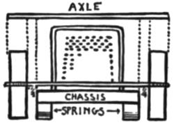
Fig. 70.
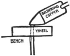
Fig. 71.
To do this, place the wheel flat on the edge of the bench so that the axle hole is just over the edge and so that the axle may be held against the side of the bench. Hold the wheel and axle firmly in this position and lay the hot soldering copper, well charged with solder, on the end of the axle wire just above the wheel.
The end of the axle will heat up very quickly and the solder should run down and form a puddle about the axle when that part of the wheel next the axle is heated up to the flowing point of the solder. The end of the axle should not project more than ⅟₁₆ inch beyond the wheel and the soldering copper[143] should be heated thoroughly and be well charged with solder, see Fig. 71.
The wheels need only be soldered to the axle on one side of each wheel if the holes for the axle fit it very snugly.
Another method of holding the wheel in position on the axle while being soldered is to drill a hole exactly the same size as the axle through a fairly thick block of wood and to push the axle through this hole until just enough of it projects so that when the wheel is slipped over it ⅟₁₆ inch of the axle will project beyond the wheel. The wooden block may then be placed in the vise and the wheel slipped over the axle and soldered to it. The hole drilled through the block must be drilled at right angles to the face of the block where the wheel is to rest. A hole may be drilled at right angles to a wood or metal surface by using a bench or post drill if you have one. Wheels may be set on the axle very accurately by this last method.
When one wheel is soldered to each axle lay them aside and make some washers for the axles before the two remaining wheels are soldered on. These washers are placed on the axles between the frame and each wheel to keep the wheels from running against the truck.
Strip Washers.—These washers may be made from narrow strips of tin wound around the axles like a tightly coiled clock spring.
Cut a strip of tin ³⁄₁₆ of an inch wide and 8 inches long. Take a pair of round-nosed pliers and bend one end over at a sharp curve that fits about the axle wire. Hold the curved part of the tin to the axle with the flat-nosed pliers and wind the tin around the wire in a right coil taking fresh grip on the tin strip with the pliers each time the tin is wound around. Wind the tin about the axle four times and then cut the remaining tin away and use it to make the other three washers, see Fig. 72.
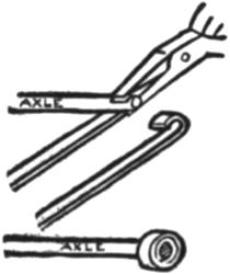
Fig. 72.
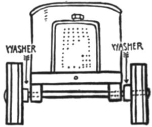
Fig. 73.
Slip one washer on one of the axles next to one of the wheels soldered to it; then push the axle through the axle holes in the springs and then place another washer on it before placing another or second wheel on the axle.
The washers are not soldered in place but simply left loose on the axle.
The second wheel is placed on the axle and soldered[145] to it as the first wheel was. The truck may be placed on its side to bring the second wheel into a convenient position for soldering. Be sure that the axle turns easily in the axle holes and that there is plenty of room for the washers between the sides of the frame and the wheel before soldering the second wheel in place. The second wheel may be soldered on the second axle in the same way and then the chassis is finished and ready to run, see Fig. 73.
Various bodies may be placed on the rear of the chassis and a steering wheel, crank and lights may be added when it is thus far successfully completed, and these will be described in the next chapter.
Do not be discouraged if you have managed to get more solder about the truck than seems necessary, as it may be scraped away as described in Chapter XXI, page 200.
TRUCK BODIES—DIFFERENT TYPES OF BODIES TO BE FITTED TO THE SAME CHASSIS—THE TANK TRUCK—THE STREET SPRINKLER—THE COAL OR SAND TRUCK—THE ARMY TRUCK—THE AMBULANCE—THE FIRE ENGINE
A permanent body of a certain type may be soldered directly to the rear part of the chassis or slides may be soldered to the rear part of the chassis and different types of truck bodies arranged to fit into these slides so that one chassis may be arranged to hold a number of different bodies. A coal truck may be transformed into a tank truck and from a tank truck into an army truck or an ambulance, etc.
A driver’s cab may be fitted over the seat and any number of realistic details added to the truck, limited only by the ability of the maker.
The wagon body is the simplest to make, as it may be made from a square can with rounded corners. The two quart or gallon cans that have contained olive or cooking oils make up into very realistic truck bodies. The body of the army truck shown in the frontispiece was made from a two-quart[147] can that had contained a cooking oil of a very well-known brand.
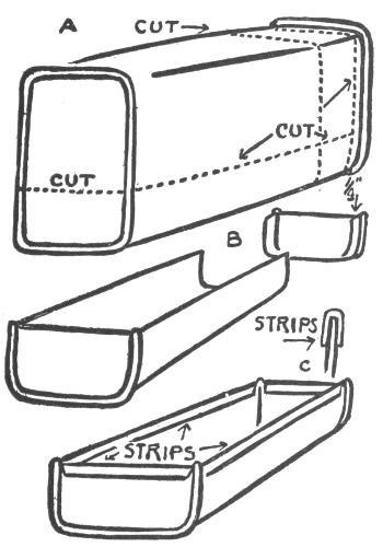
Fig. 74.
The object is to find a rectangular can that is just about the width of the chassis so that the tops of the wheels will clear it nicely. Cut the can in two lengthwise, using the file to cut through the rounded or rolled rims, see Fig. 74, A.
The can will probably be too long for a well[148] proportioned body and will have to be cut down to a suitable length, about 7 inches. Truck bodies usually overhang the chassis. Study some of the big trucks seen on the streets, as some of them are remarkably easy to reproduce.
If the can has to be shortened, use a can opener or the double cutting shears and cut around the can 1 inch from either end until one end of the can is completely cut away, then cut the shorter end down to ¼ inch at the side, leaving that much of the side of the can so that it may be slipped inside the other or larger part of the can when that part of the can is cut down to a suitable length, when the shorter end is soldered in place to form the end of the body, see Fig. 74, B.
When one end is cut off the can, cut the can in two lengthwise so that the part to be used is about 1½ inches high, and then cut off the shorter end so that it is also 1½ inches high to correspond to the other part of the body. Then fit in the end of the can and solder it in place.
Cut four strips of tin ½ inch in width, two of them as long as the two sides of the can and two as long as the ends and fold these strips over to make a protection for the top edges of the body just as you did for the lower edges of the chassis. Solder these strips in place and the body is finished and ready to be soldered to the truck, see Fig. 74, C.
Different Types of Bodies to be Fitted to the Same Chassis.—The body described above may be soldered directly to the chassis of the truck or to a strip of tin and so arranged as to slide onto the chassis between two slides made of folded tin. These slides are soldered directly to the chassis in the rear of the seat and the different types of bodies arranged to fit between them, thus using the same chassis for as many different types of bodies as one cares to make for it.
The fixed slides should be made of two ½-inch strips of tin as long as the back or floor of the chassis, about 6 inches. These strips are folded over into a gutter shape as are the strips used to protect the bottom edge of the truck frame, but the folded strips used for the slides are left somewhat more open, about ⅛ inch between the edges, so that when soldered to the truck a strip of tin may be easily slipped between them as shown in Fig. 75.
A flat strip of tin should be cut as long as the two slides and of such a width that it will fit easily into the slides soldered to the truck to receive it. Care should be used when soldering the slides to the truck to get them parallel with the sides of the frame and also parallel with each other as shown in Fig. 75.
Several cross-members may be made of folded tin and may be soldered to the flat piece of tin that is to slide between the slides. The truck body should[150] be soldered to these cross-members so that the body will clear the fixed slides when slipped into place.
These cross-members or body supports are usually found under the bodies of large trucks and they add a very realistic touch to the model. They should be just long enough to clear the edges of the fixed slides when attached to the flat strip of tin.
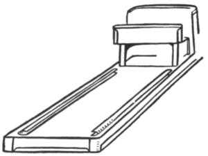
Fig. 75.
Cut three pieces of tin 1¼ inches wide and long enough to make the cross-members, about 3 inches (make sure of this measurement for yourself). Scribe a line ⅜ inch in from each of the long sides of the three pieces and then fold down two sides of each piece from the scribed lines, making three cross-members or supports as shown in Fig. 76. Solder these to the flat strip of tin that is to fit between[151] the fixed slides. The truck body should be soldered to these three supports.
A round can with the lid soldered on will make a very satisfactory tank truck. A part of a small can, such as a tooth powder can, may be soldered to the top of the tank for a filler dome and imitation faucets made of wire or of brass cup hooks may be soldered to the rear of the tank and a small delivery can may easily be made and hung on the faucets as shown in Plate XIII.
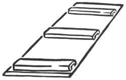
Fig. 76.
Six different types of truck bodies that may be attached to the chassis are shown in Fig. 77.
The Tank Truck.—The tank truck is made from a rectangular cooking oil can with a part of a small can soldered to the top. The faucets are made of pieces of galvanized wire bent over at an angle.
The Street Sprinkler.—The street sprinkler may be made from a large round can, such as a molasses or syrup can with the lid soldered on to make it water tight. A hole is cut in the top of the can and[152] the top, or open end, of a small soup can is soldered over the hole. The sprinkler tubes are made of strips of tin rolled around a large nail and then soldered together.
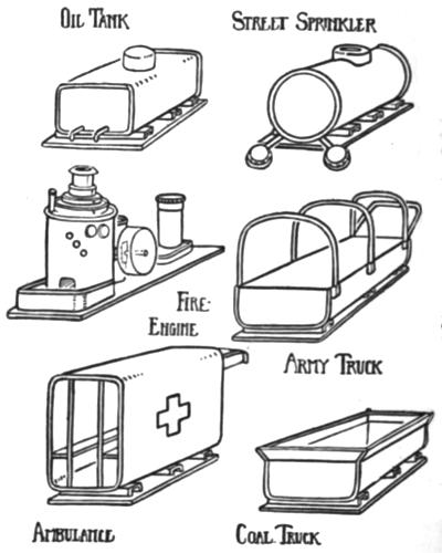
Fig. 77.
PLATE XIII
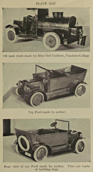
Oil tank truck made by Miss Nell Guilbert, Teachers College
Toy Ford made by author
Rear view of toy Ford made by author. Tires are made of teething rings
PLATE XIV
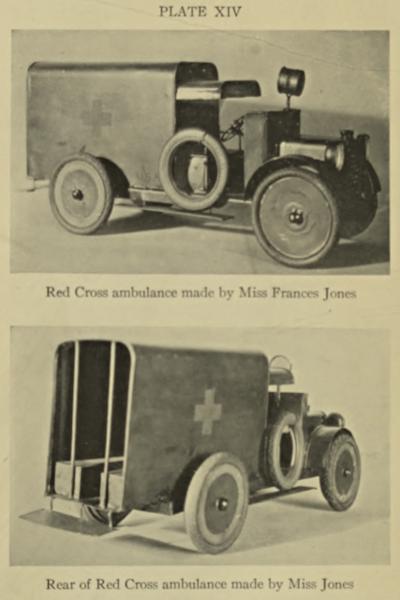
Red Cross ambulance made by Miss Frances Jones
Rear of Red Cross ambulance made by Miss Jones
The sprinkler ends are made of small round metal boxes with tiny holes punched in the under side. A hole is punched in the top of each round box and the sprinkler ends are soldered to the tubes and the tubes soldered to the tank which has holes punched in it to admit water to the tubes in such a way that the water contained in the tank will flow from the tank into the tubes and out of the sprinkler holes punched in the small boxes. These small boxes or sprinkler ends may be made of thumb tack boxes or from two bottle caps soldered together, but the crinkled part should be cut away from the bottle caps before soldering.
The Coal or Sand Truck.—The coal or sand truck body is made of less than half of a rectangular cooking oil can, the top of each side flared out and extra pieces fitted to each end so as to fit into the flaring sides and to each end. All sharp edges should be folded over or extra folded strips of tin folded over and placed over the edges of the truck body.
The Army Truck.—The army truck body is made from part of a cooking oil can. Galvanized wire of small diameter is bent into hoop form and soldered to the sides. These hoops may be covered with a khaki-colored cloth like the one shown on the large army truck in frontispiece; a khaki-colored handkerchief will make an excellent cover for a small truck.
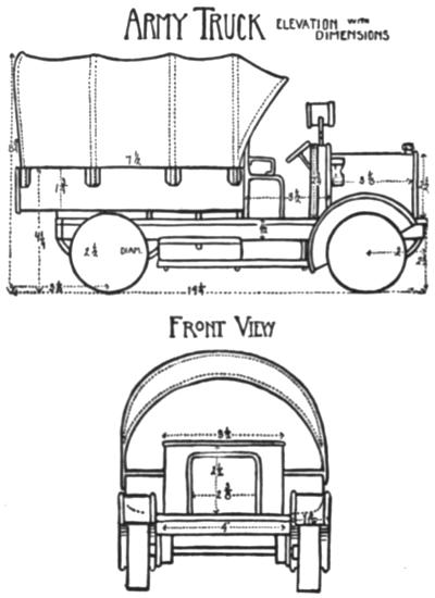
Fig. 78.
The Ambulance.—The ambulance body may be made from a large cooking oil can. Both ends are cut out of the can and the extra tin trimmed away.[155] One side of the can is cut off and a flat piece of tin soldered across the open side of the can to form the floor of the ambulance. A hood to cover the driver’s seat is made from the curved side of the can cut away to form the floor of the body. Two strips of tin may be soldered to the side of the body to form seats or stretchers and two pieces of galvanized wire may be soldered to the seats and to the floor and roof of the body to form handles. The rear step may be made of a piece of folded tin and two pieces of galvanized wire as shown. A realistic touch may be given to the ambulance by making a small curtain of carriage leather and attaching it to the rear of the roof so that it may be rolled up and fastened in place.
The Fire Engine.—The fire engine boiler may be made from a tomato can with several different sized can lids soldered to the bottom to form the smoke hood and a cylinder of tin soldered to the lids to form a chimney. The flaring top of the chimney may be made of the small center lid sometimes found in the ends of round cans. This small lid or sealer may be melted off, the center cut out of it, and then may be soldered to the top of the chimney. The steam gauge and water gauge may be made of the screw tops of cooking oil cans. The water glass may be made of a small piece of galvanized wire and the try cocks of rivets soldered to the[156] boiler. The rivets may be held in place while soldering by a pair of pliers.
The boiler platform may be made of a sardine can. The engine and pump cylinders may be made of adhesive tape boxes or strips of tin rolled into cylindrical form and ends soldered in place. The engine wheel may be made from an evaporated milk can. The air chamber may be made from a nickeled shaving stick box or a brass curtain pole ball. The whistle may be made from a used .22 cartridge case, etc.
THE STARTING CRANK—THE STEERING WHEEL AND COLUMN—MUD GUARDS AND RUNNING BOARDS—LIGHTS, TOOL BOXES, HORNS, ETC.—DRIVERS’ CABS
Various fittings may be added to the truck and these add very much to the general appearance and make the truck very realistic.
The Starting Crank.—A starting crank may be made of a piece of galvanized wire bent into a crank shape and placed in position through holes punched for it in front of the frame and through an extra piece soldered underneath the frame.
Cut a piece of galvanized wire about 5 inches in length. Fairly heavy wire will look better than thin wire when made up into a crank. Mark off 1 inch from one end of the wire and then make another mark 1 inch in from this one. Place the wire in the vise jaws so that the first mark is parallel with the top of the jaws. Use a hammer to bend the wire over at right angles, then move the wire up to the second mark and bend the wire again at right angles so as to produce a crank form as shown in Fig. 79.
Use an ice pick to punch a hole in the front of the truck frame and make it large enough so that the crank will turn in it freely.
Cut a piece of tin ¾ by ¾ inches and bend over ¼ inch at one end and punch a hole to fit the crank wire in the center of the largest side of this piece and solder it in position directly back of the hole punched in the front of the frame and in such a position that the end of the crank wire projects about ¼ inch beyond the small angle piece soldered to the frame, as shown in Fig. 80.
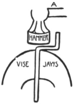
Fig. 79.
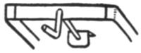
Fig. 80.
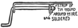
Fig. 81.
Wind a narrow strip of tin about the straight projecting end of the crank wire and solder it in place, the solder being applied to the end of the wire and to the end of the coiled strip of tin at the same time, Fig. 81.
The Steering Wheel and Column.—A steering wheel may be made of an old clock gear wheel with the teeth cut off, or a small can lid may be used instead. The steering wheel column may be made of a piece of heavy galvanized wire.
Clock gear wheels are usually fastened to a short steel shaft, but they may be easily driven off the shaft by placing the shaft of the wheel in the vise jaws so that the wheel is above the vise jaws, and then a few light hammer blows directed at the upper end of the shaft will loosen the wheel and it may be easily removed. The vise jaws should hold the shaft very loosely as it is being driven out of the wheel.
Use the metal shears to cut off the gear teeth and a smooth flat file to file down the roughness left at the edge of the wheel.
Find a piece of galvanized wire that fits into the hole in the clock wheel or file a larger piece down until it does fit. The wire should project slightly beyond the wheel and be soldered to it in exactly the same manner as the tin can wheel is soldered to an axle. The wire that the steering gear is soldered to should be long enough to go through the dash-board, hood and frame, if the wheel is to turn. A strip of tin is coiled about the wire below the frame as shown in Fig. 82. These are soldered in place to the wire to keep it in position and yet allow it to turn freely in the holes.
Mud Guards and Running Boards.—Mud guards may be made from a part of the side and bottom of a can as shown in Fig. 83. A 3-inch can is the best size to use for the truck. The can is cut down to a height of 1⅛ inches and then cut into two parts across the bottom so that two mud guards may be made from each can. The outer edges are turned as in making a tray and folded pieces are slipped over the ends as shown in Fig. 83. These mud guards are soldered to the frame in the position shown.
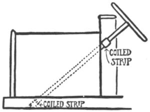
Fig. 82.
Running boards may be made of two pieces of tin, each piece to be cut 1¼ inches wide and as long as it is desired. The four pieces are each turned down ⅛ inch at the long sides and two pieces are fitted over each other to make one running board[161] as shown in Fig. 84. Two or three supports may be made of galvanized wire for the running boards. These supports extend across the frame of the truck and one end of each support is soldered to each running board. One end of each running board is usually soldered to each mud guard.
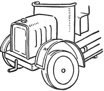
Fig. 83.
Lights, Horns, etc.—Headlights may be made of thumb tack boxes, bottle caps or the tops of tooth powder cans. Sidelights may be made from the screw caps of cooking oil cans or the cylindrical part of tooth powder can tops.
Tail-lights may be made of the screw caps of cooking oil cans.
Searchlights may be made of the smallest size adhesive tape boxes mounted on suitable standards made of galvanized wire or strips of tin.
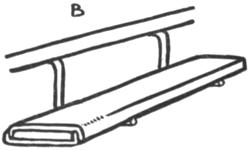
Fig. 84.
The central part of the cover of these boxes is cut away and a piece of isinglass or transparent celluloid may be fitted in to look like a lens. The central part is cut away by using a small chisel to cut with when the cover is placed over the end of a round stick held in the vise. The rough edges are smoothed away by using a smooth half-round file.
The construction of these lights is so simple as to need no further explanation and they are simply soldered to the frame or hood where they touch it when placed in position. The searchlight is usually mounted by punching a hole for the standard in the[163] cowl, or by soldering on an extra piece to the dash to receive the wire standard, Fig. 85.
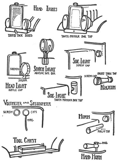
Fig. 85.
Tool Boxes, Horns, etc.—Small rectangular beef[164] cube or chewing gum boxes may be soldered to the running board for tool boxes. These boxes have rounded corners and look very much like the large tool boxes, Fig. 85.
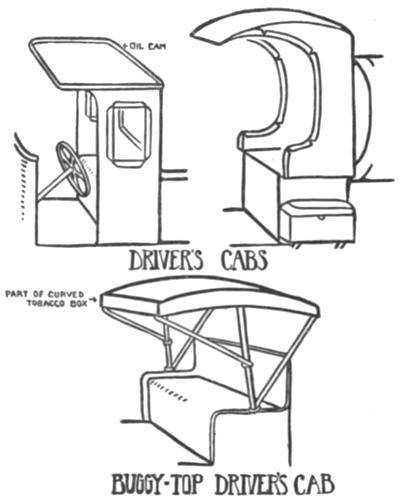
Fig. 86.
Horns may be made in several ways, the simplest form being a piece of tin rolled into a cone shape and soldered to the dash. A more realistic horn may be made by soldering a screw cap to the larger end of the cone and adding the cap of a paint tube to the smaller end. A hand horn may be made as shown in Fig. 85.
Speedometers, voltmeters and ammeters may be made of screw tops soldered inside the dash as shown.
Drivers’ Cabs.—Most of the large trucks have some kind of a cab to protect the driver from the weather, excepting the army trucks, which usually depend on part of the canvas hood or cover for protection.
On the toy trucks these cabs may be very simply made from a square tin cocoa or olive oil can or they may be more elaborately built, depending on the ability of the maker. These cabs should be carefully made and kept in proportion to the rest of the truck.
All sharp edges should be turned over or bound with folded strips of tin. Windows may be cut in the cab by placing it on the block and using a small chisel to cut them out. The edges of these windows should all be bound with folded strips of tin as shown in the illustration.
The buggy top for the driver’s seat may be made from part of a certain well-known curved tobacco box and several short pieces of galvanized wire, Fig. 86.
THE ROWBOAT—THE SAILBOAT—THE SCOW—THE TUGBOAT—THE BATTLESHIP—THE FERRY-BOAT
The elliptically shaped tin cans, used for fish of different kinds, may be made up into boats that will float. A deck is soldered tightly to the can where the lid has been removed and various superstructures added to make the different types of boats, but to form a rowboat, seats may be soldered to an open can.
The Rowboat.—The rowboat is the simplest one to make as no deck is to be soldered on. A narrow elliptical fish can should be used. These cans usually contain fresh mackerel, and are of real boat shape.
Such cans are opened at the top inside the rolled rim. The extra tin near the edge of rim should be broken away with the pliers as in making a pail, all roughness being filed away.
Lay the can face down on a sheet of paper, drawing around the outside edge with a sharp pencil to get an outline of the boat. This outline will serve as a guide when cutting out the seats. The seats may be cut to the outline of the boat already traced[167] on paper, when the two end seats will fit bow and stern. But the center seat will have to be trimmed off a bit to fit the boat. The free edges of the seats must be turned down as a finish.
The Sailboat.—A catboat or sloop may be made from the same sort of narrow elliptical can or even of a wider can of the same shape. A deck is soldered to this can, a hole cut in it for a cockpit. To the edge of the cockpit a folded band of tin is soldered.
A tube of tin is soldered to the stern, and a wire tiller is run through this tube and soldered to a rudder. A hole is punched in the center of the forward deck, and a tube of tin is soldered in this hole to contain the mast. The mast and spars are of wood.
The keel is made of a piece of tin soldered to the bottom of the boat. The boat should be completed, and the mast, spars and sails in place, before the keel is put on. Try the boat in a basin of water. It will probably tip over unless a very broad can is used to make it. Cut out a keel of the shape shown in Fig. 87 and solder it lightly in place at each end. Place the boat in the water again to see how it floats. If the keel is too heavy, part of it may be cut off, if it is too light, it may be broken away and a heavier one made and soldered on. When properly made these boats are good sailers.
When soldering a deck to the boat, the rough edge remaining after cutting away the lid of the can is left in place so as to form a sort of ledge to[168] solder the deck to. The rough flutings may be flattened out by using a pair of flat-nosed pliers to[169] press down the flutes as you work along and simply pinching it flat.
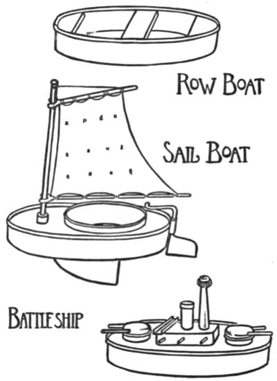
Fig. 87.
The Scow.—A small scow may be made from a biscuit box of flat tin, the kind that has contained small sweet biscuits with a cream filling. Both box and lid are used and cut down as indicated in Fig. 88. The box is left at the original width. The two ends are cut away from the lid. The two folded-down sides of the lid are used to make folded strips with which to bind the sides of the scow.
A tiny box made of part of the lid is soldered to the rear deck of the scow for a cabin. A small piece of galvanized wire bent at an angle is soldered to the cabin for a stovepipe. The towing bits are rivets soldered to the forward deck.
The Tugboat.—Tugboats may be made from the larger elliptical fish cans. A good sized can of this sort is that one commonly found to contain kippered herring. This can will make up into a large tugboat, but if a small tug is to be made to tow the scow previously described, a mackerel roe can is the best to use.
A deck is soldered tightly to the can, as in making the sailboat, except that the deck is left whole; no openings are cut in it.
The cabin is made from a rectangular cocoa can, or a small olive oil can, cut down to a suitable height and soldered to the deck, bottom up.
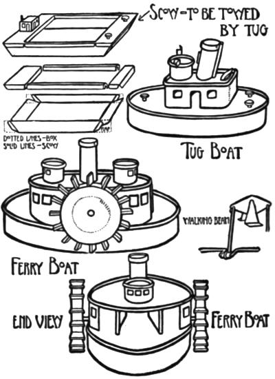
Fig. 88.
The pilot house is made from a small adhesive[170] plaster box, the smokestack being from a small piece of tin with top edge first folded over and then rolled[171] into a cylindrical shape. A piece of wire may be soldered to the stack for an exhaust pipe. A tiny piece of wire is soldered to the front of the stack for a whistle. These pieces of wire may be tied to the stack with fine iron binding wire, such as florists use. When the wire exhaust and whistle are soldered to the stack the wire may then be removed. It will be found very difficult to solder these short pieces in place without binding them in position.
PLATE XV
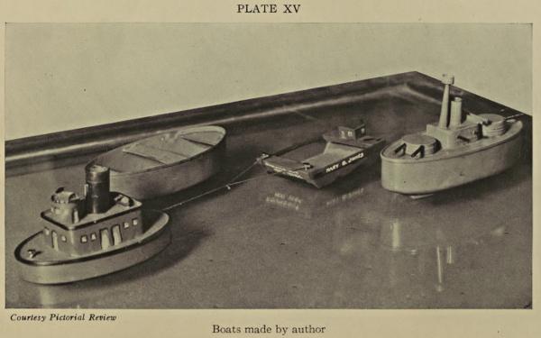
Courtesy Pictorial Review
Boats made by author
The lifeboat is made from a small folded piece of tin, both ends being pushed in and soldered together. The finished boat is soldered to the roof of the cabin.
The towing bits are rivets soldered to the deck. Remember to use the pliers to hold the rivets in place when soldering them on. When these boats are floated in the water they may be found to tip to one side slightly. A bit of solder may be melted on to the bottom of the boat with the copper in such a position that it will counteract any tendency to tip.
The Battleship, Destroyers, etc.—The battleship shown in Plate XV is made from a narrow elliptical fish can. A deck is soldered on and a cabin made of a small rectangular box such as beef cubes usually are packed in.
The turrets are made of pill or salve boxes of small round tin design. The lid of the box is soldered to the deck and when the box is set in the lid the turret may be turned about.
The guns are made of short pieces of wire soldered to the turrets and cabin.
The mast is made of a tin oil can spout or a piece of tin rolled into a cone shape. A screw cap of a tooth paste tube is soldered to it for a fighting top.
Some sort of a keel will have to be soldered to the battleship to keep it upright in the water. Three pieces of heavy galvanized wire may be soldered to the bottom, one in the center and one at each side, or a strip of sheet lead may be soldered to the bottom.
A destroyer may be built up in the same manner as the battleship; in fact, almost any type of boat may be built by changing the superstructure.
The Ferry-boat.—A ferry-boat may be built with paddle wheels that will revolve when the boat is pulled along in the water or anchored in a running stream.
The hull is made from a kippered herring can with a deck soldered on. Four strips of tin are cut for the sides of the cabins. Two of these are soldered to the sides of the hull next to the rolled rim and following the outline of the can or hull. The two inside walls of the cabins are soldered about ¾ of an inch inside the outer walls which leaves a gangway through the center of the boat.
An upper deck is soldered to these four walls; the inner walls need only be soldered to the upper deck at each end.
The two pilot houses are made of adhesive plaster boxes and the smokestack is rolled up from a piece of tin.
A hole is punched or drilled through all four walls of the cabin to receive the axle of the paddle wheels.
The paddle wheels are made from small cans exactly in the same way as the auto truck wheels and eight small square pieces of tin are soldered to the circumference of each wheel for paddles. Rolled strips of tin are placed on the axles between the wheels and the cabins for washers. The axle should revolve very freely in the axle holes.
If one has some mechanical ability it is not very difficult to form a crank in the paddle wheel axle and attach a connecting rod to a small tin walking beam which will move up and down as the paddle wheels revolve. An imitation piston rod may be fastened to the other end of the walking beam and allowed to run free through a hole in the upper deck.
The wheels of the ferry-boat will revolve if it is anchored in a running stream or towed behind a rowboat.
A SIMPLE TOY LOCOMOTIVE—THE FRAME—BOILER—CAB—WHEELS—CYLINDERS AND CONNECTING RODS—THE SMOKESTACK, STEAM DOME AND WHISTLE, SAND BOX AND HEADLIGHT—CARS—A PASSENGER CAR AND SOME OTHERS
The locomotive shown in Plate XV is made so that the connecting rods move back and forth as the locomotive is pulled along. The principal dimensions are given in Fig. 89. This locomotive is not much more difficult to make than the auto truck, but it should not be attempted until the auto truck is satisfactorily completed.
The Frame.—The frame of the locomotive should be made first, and it is made from a flat piece of tin 5¼ by 10½ inches. Scribe a line ¼ inch inside and along all edges, cut off the corners as shown in Fig. 89 and fold all four edges in. Cut into the corners of the frame on lines A, A, A, A.
PLATE XVI
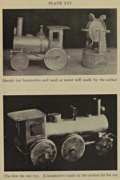
Simple toy locomotive and sand or water mill made by the author
The first tin can toy. A locomotive made by the author for his son
PLATE XVII
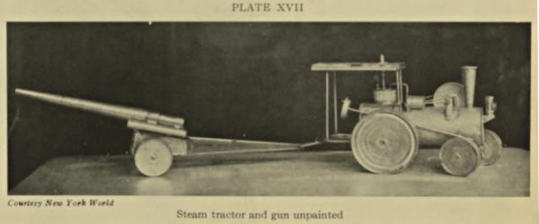
Courtesy New York World
Steam tractor and gun unpainted
Turn down the two sides of the frame first, then turn down the two ends. The four pieces of the sides that project beyond the sides are turned in over the ends as shown in Fig. 89. The sides and ends of the frame may be turned over a square maple block. Solder the frame at the ends.
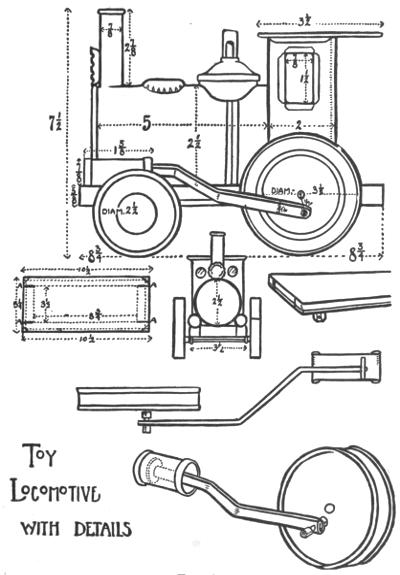
Fig. 89.
The Boiler.—The boiler is made of two small soup cans. One whole can is used and the bottom and part of the sides of another can of exactly the same size is soldered to the first can to make a long boiler. One long can, if obtainable, may be used for the boiler. When two or more cans are soldered together to make a long boiler the two rolled rims of the cans soldered together give the appearance of a boiler strap as shown in Fig. 89.
The Cab.—The cab is made of a rectangular cocoa can. Most of one side is cut away leaving just enough to fold back against the sides of the cab. The cab is then placed on a wooden block and a chisel is used to cut the window openings. A large round punch may be used to cut out the front windows or a very small chisel made of a nail may be used to cut these circular windows.
A top is made for the cab from a piece of tin 3¾ by 3¾ inches square. One-quarter inch is marked off and turned in all around this piece. Two opposite sides are folded down and the two other sides are left standing at right angles to the piece and these two opposite sides are left open just enough to slide over the top of box forming the cab where the top is soldered in place as shown in the drawing.
The boiler should be soldered to the cab and then these two are soldered to the frame where they touch it at the front end of the boiler and the base of the cab.
The Wheels.—The front wheels of the locomotive are made of the small sized evaporated milk cans exactly in the same way that the wheels of the auto truck are made. These wheels are 2½ inches in diameter and ⅝ inch wide.
The wire axle of the front wheels passes through two lugs that are soldered to the sides of the frame.
The driving wheels are made from 3½-inch rolled-rim cans. The axle for these wheels passes directly through holes in the sides of the frame.
A piece of galvanized wire 1¼ inches in length is used for driving pins for the connecting rods on each driving wheel. Each piece of wire is placed through two holes in the driving wheel, these holes being directly opposite each other and exactly ½ inch from the center of each wheel. As these driving pins pass entirely through the wheel they should be soldered to each side of it in order to give added strength, as they would break away from the wheels very easily if they did not pass entirely through the wheel and were not supported by each side of it.
Cylinders and Connecting Rods.—These cylinders are rolled up from flat pieces of tin each 2¼ by 3¼ inches. The tin is folded over on the two shortest sides of each piece before it is formed into a cylindrical shape, the folded sides of the tin forming each end of the cylinders.
The connecting rods are made of two strips of tin, each ¾ by 6¼ inches. Both sides of the strip[178] are folded in, making a triple thickness of tin and a connecting rod about ⁵⁄₁₆ inch wide and 6¼ inches long.
A disk of tin is soldered to one end of each connecting rod. These disks should be somewhat smaller than the diameter of the cylinders so that they may slide easily back and forth inside the cylinders.
The connecting rods have to be bent at the two angles shown in Fig. 89 so that each rod may be in line with the cylinder and with the driving wheel.
The Smokestack, Steam Dome and Whistle, Sand Box and Headlight.—The smokestack is rolled up from a piece of tin 2¾ by 2⅞ inches. This piece of tin is cut from the side of a can so as to leave the rolled rim at the top for the rim of the stack.
The steam dome is made of the top part of a tooth powder can with the distributer top left on. This top is left open to form a whistle. That part of the tooth powder can which rests against the boiler must be fitted very carefully so as to conform to the curve of the boiler.
The sand box may be made from a bottle cap and the headlight may be made from another bottle cap as shown in the drawing.
Cars.—A coal tender for the locomotive may be made from a small square box mounted on a frame or platform similar to the locomotive, only smaller. The car wheels may be made from the small evaporated milk cans or from any small cans obtainable.
A freight car may be made from a long square box in a manner similar to the coal tender. Passenger cars may be made from long rectangular cans and the windows and doors may be cut or painted on the sides or ends. Be sure to place folded strips of tin over any raw edges left when cutting out windows and doors.
A Passenger Car and Some Others.—A passenger car may be made from an olive or cooking oil can; that is, about half of one of the larger cans cut lengthwise. Select a can so that when it is cut lengthwise to dimension it will be in proportion to the locomotive which is to be used with it. No dimensions are given in the drawings as these cans vary in size, but it is not difficult to find a suitable rectangular can for a passenger car.
When the can is cut open, draw two parallel lines along the sides for window openings. Do not try to cut each window separately, but cut one long opening for all the windows, bind the cut edges with folded strips and then solder folded pieces across the window openings at intervals for divisions between the windows.
Cut a door in each end of the car and bind the edges with folded tin. The projecting hoods over the door at each end of the car roof may be made of part of the sides and bottom of a square can or from that part of the olive or cooking oil can that is cut away in making the body of the car.
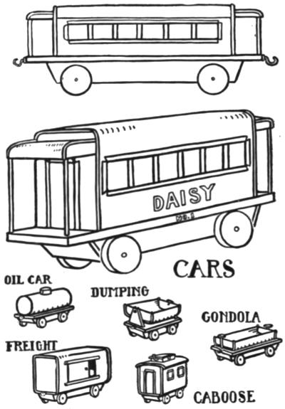
Fig. 90.
A flat piece of tin may be used for the bottom of the car, this piece being formed in exactly the same way that the frame of the auto truck is formed. It is made long enough to allow for a platform at each end of the car, and the car body is soldered securely to it.
Car wheels may be made from very small cans as any other tin can wheels are made. Two bottle caps may be soldered together for a wheel or several flat disks of tin may be cut and soldered together at the edges to form a wheel. The tin washers used with roofing nails make an excellent wheel when two are soldered together, back to back. Never try to use a single can lid, bottle cap or tin disk for a wheel that is to bear any weight. Any of these are too weak to stand up alone. The wheels are mounted in the manner shown in the drawings of the passenger car.
Other cars may be made from cans as shown in Fig. 90, the construction being so simple as to need no further description. These cars may be made as simple or as elaborate as the skill of the maker permits.
WATER WHEELS AND SANDMILLS—A SIMPLE STEAM TURBINE AND BOILER—A WINDMILL AND TOWER—AEROPLANE WEATHERVANE
Water wheels and sandmills may be made from bottle caps and can lids. Two push-in or friction-top can lids are soldered together to form a flanged wheel and bottle caps are soldered between the flanges, at equal intervals, for the buckets. The general construction is shown in Fig. 91. A nozzle may be formed from a piece of tin and soldered to the standard so that a hose may be connected with it and to faucet, or, the water wheel may be set in a sink under a faucet or placed in a stream of running water.
A funnel or sand hopper may be made of tin and soldered to a standard which holds the bucket wheel. Fine dry sand placed in the hopper will run through the hole in the bottom and cause the bucket wheel to revolve.
A Simple Steam Turbine and Boiler.—A very simple and amusing steam turbine that runs with steam generated in a tin-can boiler may be made from tin cans. Select a well-soldered can with a[183] tight-fitting lid, such as a molasses or syrup can with a friction-top lid. The lid will have to be soldered in place to make it steam tight.
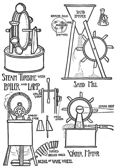
Fig. 91.
Punch a hole about ¼ inch in diameter near one side of the lid for a filler hole. See that this hole is perfectly round so that a cork may be fitted in to make it steam tight.
The vane wheel should be about 3 inches in diameter and very carefully made. See that the axle is soldered exactly in the center of the wheel. The vanes should be small and numerous and each one exactly the same size. The method of construction is shown on page 183 (full page drawing). A 3-inch circle is carefully laid out on a flat piece of tin and then another circle is laid off inside the first one about ¾ inch in. The outer circle is then divided up into 36 equal parts. Draw straight lines from each dividing dot at the edge to the center of the wheel. Bore a small hole exactly where each line crosses the inner circle. Cut down each dividing line to each hole. Use the pliers to turn each vane at right angles to the face of the wheel.
The steam nozzle should be very small. A triangular piece of tin may be formed around a fine wire nail or pin. The opening in the nozzle should be about ⅟₃₂ inch in diameter. The nozzle should be well soldered together and then soldered to the boiler, over a hole of a suitable size to allow the steam to flow from the boiler into the nozzle. Be[185] sure not to solder up the tube so that the steam may not escape. A piece of broom straw may be placed in the nozzle when soldering it together, and it may be left in when the nozzle is soldered to the boiler. The straw should extend into the boiler and may be withdrawn when the soldering operations are completed. Do not use wire inside the nozzle to prevent it filling with solder as the solder will stick to it and prevent its being withdrawn.
Use care in placing the nozzle in position under the vane wheel so that the steam will strike the vanes squarely when it escapes. Set the end of the nozzle as close to the vanes as possible, but so that it does not strike the vanes when the wheel revolves.
These turbines run at very high speed when carefully made. Do not use too much heat under the boiler, as too great pressure may explode it with disastrous results. If the boiler is set over a gas flame, take care not to allow the flame to flare out around the boiler and creep up the sides, as it may then melt off the top of the boiler even when there is considerable water in it. A moderate flame will cause enough pressure to be generated in the boiler to make the vane wheel revolve rapidly. If care is used in fitting the cork in the filler hole, it may be made steam tight by pushing it into the filler hole with a light pressure so that if too much pressure is generated in the boiler the cork will blow out.
A pinion from a small clock works may be[186] soldered to the vane wheel shaft and meshed in with a large gear which is set on a shaft soldered to the supporting upright at one side of the wheel. A small pulley may be made of wood or metal and fastened to the large gear. This arrangement of gears will give a reduced speed and a string belt may be run from the pulley to some light running toy machine. The pinion and gear fastened to the turbine should run very easily.
An alcohol heating lamp may be made for the turbine boiler by soldering a wick tube and a vent tube to a shoe paste or salve box.
The wick tube should be made from a strip of tin rolled up into a cylindrical shape. It should be about ½ inch in diameter and 1½ inches in length when soldered together. The wick tube should extend about 1 inch above the top of the lamp and it should be soldered firmly in a hole cut in the top of the lamp to receive it.
A small tube about ¼ inch in diameter and 3 inches long is soldered together. This tube should be soldered over a hole near the side of the lamp at the top and soldered on at an angle as shown in Fig. 91. It serves as a vent, allowing the alcohol gas generated within the top of the lamp to escape and it also serves as a handle. An alcohol lamp fitted with a vent tube of this description will not boil over and catch fire as so many of the small alcohol lamps provided with toy steam engines are[187] sure to do. Vent tubes soldered to these lamps in such a manner as to conduct the gas away from the flame will provide against accidents of this sort.
A filler hole should be placed in the top of the lamp as far away from the wick tube as possible. A common cork may be used as a stopper. A small funnel may be easily made from some pieces of scrap tin and used for filling the boiler and the lamp.
A Windmill and Tower.—A windmill and tower that will look very realistic when completed may be made from tin cans. The vane wheel is composed of twelve blades set in two can lids. The vanes are cut from a flat piece of tin, care being taken to make each one exactly the same size. A large can lid is used for the outer vane support and the central part of this lid is cut away. Twelve cuts are made around the edge of the can lid at equal distances and the vanes soldered in these cuts.
A small can lid is used for the center of the wheel and the ends of the vanes soldered to it.
The tower is made of strips of folded tin and the tank from a tin can is shown in Fig. 92.
Aeroplane Weathervane.—A biplane weathervane may be made from flat strips of tin. Large round or square cans may be opened out and the tin taken from them used to make the aeroplane weathervane. When this weathervane is mounted on a suitable spike on which it may turn about freely in the wind, the propeller will revolve rapidly when the wind blows.
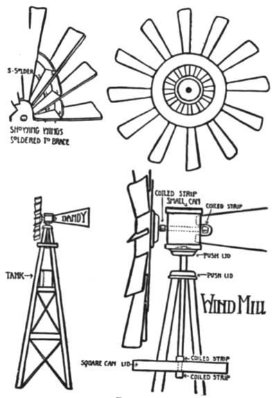
Fig. 92.
PLATE XVIII
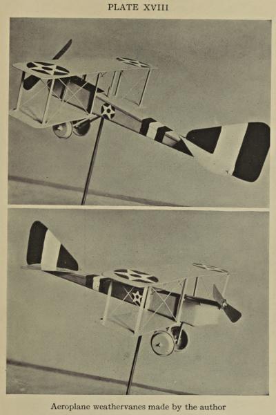
Aeroplane weather vanes made by the author
The construction of the aeroplane is quite simple and the principal dimensions are given in Fig. 93. The construction is very well shown in Plate XVIII. If the foregoing problems have been satisfactorily worked out there will be no difficulty in constructing the aeroplane from the dimensions given.
The two wings are made from two pieces of tin of the required size with the edges folded over.
The body of fuselage is made of a long triangular piece of tin folded up on each side so as to form a sort of long tapering box. A cover is made for this box and divided into two parts so as to leave a cockpit opening.
The struts or wing supports are made from narrow strips of tin that are folded almost together for strength. The small guy wires had best be made from copper wire of small diameter. If it is difficult to get small copper wire, it may be possible to get two or three feet of insulated copper wire used for electrical purposes. Such wire is employed to wind small magnets used on electric bells. The insulation easily burns off. Copper wire solders very easily.
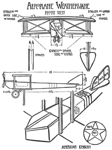
Fig. 93.
The rudder and tail planes are made from flat pieces of tin. A straight piece of wire is used for the propeller shaft. A tube is made of tin and used as a bearing for the shaft. The propeller shaft should fit very loosely in the tube. The bearing tube[190] is soldered firmly to the body of the aeroplane as shown in Fig. 93. When completely assembled, except for the propeller and its shaft, the propeller is soldered to one end of the shaft. Care should be[191] taken to mount the propeller blade in such a way that the shaft is exactly in the center, so that one side of the propeller is not heavier than the other. The shaft is pushed through the bearing tube and should project about ¼ inch beyond it. A strip of tin is wound around this projecting end of the shaft and soldered to it in such a manner that the shaft is free to turn in the tube.
When the plane is completely assembled try it to find the point at which it balances when rested on the finger under the fuselage. A hole should be punched at this point large enough to admit the iron rod or piece of heavy wire that is to be used for the spike on which to mount the weathervane. A second hole is punched directly above the first one; this hole is considerably smaller than the hole beneath it. The top of the iron spike that supports the aeroplane weathervane is filed down to a smaller diameter so that when the spike is pushed through the larger hole the smaller or filed part of the spike will go through the hole in the upper part of the fuselage. The weathervane will then rest on the shoulder formed on the spike as shown in the illustration. A block of wood may be nailed to the roof peak of the house or barn and a hole bored into it the size of the supporting spike, and the spike may be pushed into this and the aeroplane weathervane mounted on the spike. It should be well painted in bright colors and if well made will prove a very pleasing toy.
WALL SCONCES, AND A LANTERN
The base of the tall candlestick shown in Fig. 94 is made of various sized cans cut down to tray-like forms and soldered together. As may be seen by studying them, the shafts are made from ordinary tin campaign horns. The drip cups are made of press-in can lids or from small cans cut down to tray-like shapes. All sharp edges are to be turned over. The candle sockets are formed in the same way as that of the candlestick described in Chapter VIII, page 94.
The wall sconces are made of large olive or cooking oil cans or the cans that have contained automobile lubricating oils. All edges should be turned or bound with folded strips of tin. Sconce No. 2 may be made of a flat sheet of tin and half of a large round can cut down to tray size. Sconce No. 3 may be made of a large round can cut down to shape.
PLATE XIX
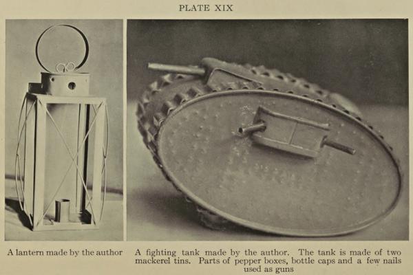
A lantern made by the author
A fighting tank made by the author. The tank is made of two mackerel tins. Parts of pepper boxes, bottle caps and a few nails used as guns
The lantern is not made from a rectangular can, but it is made from two square pieces of tin used for the top and bottom, part of a can being fitted in a hole cut in the square piece used for the top of the[193] lantern. The four corner pieces of the lantern are made of strips of tin cut at a right angle.
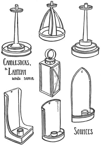
Fig. 94.
A sliding door is made from a flat sheet of tin, this door sliding between two folded strips of tin which are soldered to the framework of the lantern. Three pieces of glass are used for the lantern, as these are held in place by small pieces of tin folded at an angle, one part of which rests against the glass and the other part is soldered to the tin work of the lantern. These pieces are put in place as each piece of glass is placed in the lantern, one at the top and the other at the bottom of each piece of glass.
A COFFEE POT—BOILING PAILS—FRYING PAN—TOASTER—A CAMP SHOWER BATH—CANTEEN OR HOT WATER BOTTLE—A MATCH BOX
An excellent coffee pot may be made from a gallon can or from a smaller one. This tin must be of the rolled rim or locked seam type so that it will not melt apart or leak if it should accidently boil dry.
Lugs are riveted to the side of the can as described in making a pail in Chapter IX, page 100. A series of small holes are punched in a triangular formation in such a manner that they will be immediately back of the spout when this is soldered in place.
The spout is made of a separate piece of tin of a triangular shape. This piece of tin is formed into shape and is then riveted to the coffee pot over the strainer holes. After it is held in place by the rivets it is tightly soldered so that it will not leak. The rivets are to prevent the spout from melting off.
A lid for the coffee pot may be made from the bottom of another can of the same size. Some cans are provided with a cover and these make excellent coffee pots.
Boiling or Cooking Pails.—The boiling or cooking pails are made in the same manner as the pails described in Chapter IX, page 100. Care should be taken to use only rolled rim or locked seam pails for any utensil that is to go over a fire.
Frying Pan.—The frying pan is made by cutting down a large round or square can of the rolled or locked seam type. The edges are turned and a suitable handle is riveted on as shown. Be sure to rivet all joints that are to be subjected to the heat from a fire.
Toaster.—A toaster or broiler may be made from folded strips of tin which are strongly riveted together as shown in Fig. 95. Be sure to put two rivets in each corner of the toaster.
The Canteen or Hot Water Bottle.—The canteen or hot water bottle may be made of two cake or pie tins soldered together or from large round gallon cans cut to size and made up like a large tin can wheel. A water-tight screw cap may be fitted to the canteen by removing the screw top and cap from a maple syrup or automobile oil can and soldering the screw over a suitable hole in the canteen. Most of these screw caps may be melted off the original can by simply heating them, the cap itself being removed during this operation.
PLATE XX
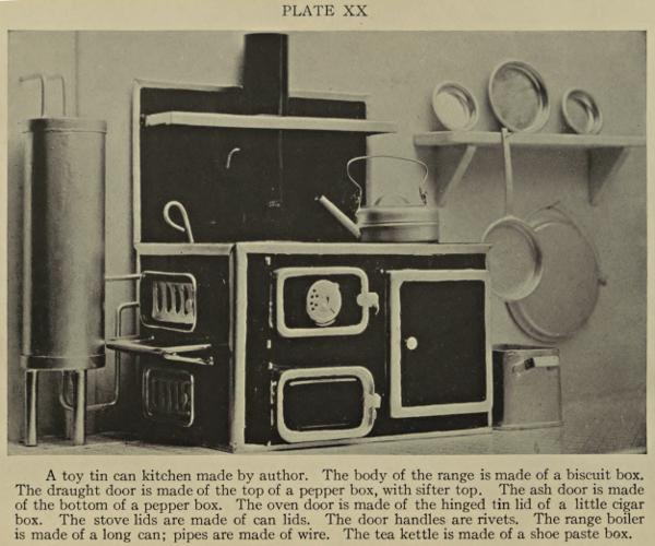
A toy tin can kitchen made by author. The body of the range is made of a biscuit box. The draught door is made of the top of a pepper box, with sifter top. The ash door is made of the bottom of a pepper box. The oven door is made of the hinged tin lid of a little cigar box. The stove lids are made of can lids. The door handles are rivets. The range boiler is made of a long can; pipes are made of wire. The tea kettle is made of a shoe paste box.
PLATE XXI
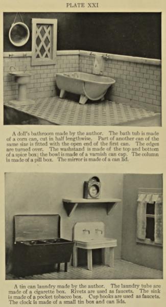
A doll’s bathroom made by the author. The bath tub is made of a corn can, cut in half lengthwise. Part of another can of the same size is fitted with the open end of the first can. The edges are turned over. The washstand is made of the top and bottom of a spice box; the bowl is made of a varnish can cap. The column is made of a pill box. The mirror is made of a can lid.
A tin can laundry made by the author. The laundry tubs are made of a cigarette box. Rivets are used as faucets. The sink is made of a pocket tobacco box. Cup hooks are used as faucets. The clock is made of a small tin box and can lids.
A Camp Shower Bath.—A camp shower bath may be made of a very large can, a shoe paste box, a[197] short length of rubber hose and two small flat pieces of tin.
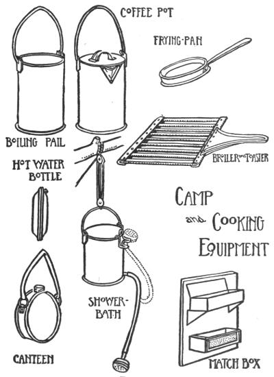
Fig. 95.
A 5-gallon can that has contained automobile oil is easily found and a hot lye bath will remove all traces of the oil. The lye solution is placed in the can and raised to the boiling point. It is then poured out and the can is rinsed with hot water.
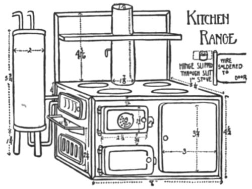
Fig. 96.
The top of the can is removed and a strong handle fixed to the can. A small nipple of tin is soldered to the side of the can, near the bottom. This nipple is simply a flat piece of tin rolled into a cylindrical shape and of a suitable size so that a piece of rubber hose may be fitted tightly over it.
A second nipple of the same size should be made for the spray nozzle. The spray nozzle is made from[199] a shoe paste or salve box. A number of fine holes are punched in the box lid and the tin pipe or nipple is soldered in a hole made for it in the bottom of the box.
A wire hook is provided at the rim of the pail to hold the spray nozzle in place when it is not desired to have the water run out of it.
It will be found convenient to have a double pulley and rope rigged to hoist the pail to a convenient height after filling.
The Match Box.—The match box is made of two cigarette boxes, one for good matches and the other for burned matches. These boxes are of ample size to hold the paper drawer of a large box of parlor matches.
The hinged top is left on the box that is to hold the unburned matches. This box is soldered to two supporting brackets in such a manner that it is held away from the piece of tin forming the back for the two boxes and so that the lid of the upper box may be raised. The lower box is simply soldered to the back piece. Three folded strips of tin are soldered to the front of this second box to form a holder for a strip of sand paper to strike the matches on.
REMOVING SURPLUS SOLDER WITH SCRAPERS—MAKING A HOE SCRAPER—PLUMBERS’ AND ROOFERS’ SCRAPERS—SCRAPING AND FILING—BOILING THE TOYS IN A LYE BATH—VENT HOLES
It frequently happens that more solder is applied to the joints than is needed to cement the work together or that the solder is left in a rather rough or lumpy state due to the inexperience of the worker.
The beginner should be in no wise discouraged if this is so, for there is a certain knack in soldering neatly and this is only acquired by experience and by closely observing the simple rules governing the operation.
The beginner should be sure that enough solder is applied to hold the work firmly together. The surplus solder may be scraped away by using a simple scraper shaped like a hoe. An old knife is also useful for cutting away lumps of solder. An old file or rasp which has very coarse teeth may be used to file away solder. A finely cut file should never be used to file solder as the fine teeth will clog up with solder and the file be rendered useless for any further work.
Making a Hoe Scraper.—A hoe scraper may be made from a cheap screw driver, such as those obtainable from the 5-and-10 cent stores. The end of the screw driver that is applied to the screw is heated red hot (a dull red). It is then placed quickly between the jaws of a vise so that the jaws grasp it about ½ inch from the end and before the steel has time to cool, it is bent over like a hoe, see Fig. 97.
Use a flat fine-toothed file to file the cutting edges to about the angle shown in the enlarged drawing of the working end of the hoe scraper.
When the tool is filed into shape, heat the end again to a dull red and plunge it quickly in a pail of water several times until it is entirely cold. The tool is then ready for use.
The hoe scraper is a very simple tool to use. The cutting edge is simply dragged with slight pressure over the solder to be removed, and will remove a little solder each time it is dragged over it. This tool may be sharpened easily with a smooth file or on a grindstone when it becomes dull.
Do not try to remove too much solder at once and do not take away too much solder from the joint as you will weaken it. Simply smooth up the solder so that it will look well when painted over.
Plumbers’ and Roofers’ Scrapers.—Two very handy scrapers may be purchased from a dealer in tinners’ tools. One of them is called a Plumbers’ Scraper and is shown in Fig. 97. The other is called[202] a Roofing Scraper and is shown in Fig. 97. Either of these tools will prove very useful for removing solder.
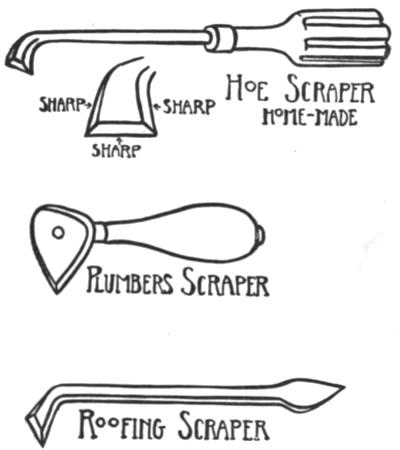
Fig. 97.
Boiling the Toys in a Lye Bath.—When the toys are completely assembled and before they are painted they should be thoroughly boiled up in a lye[203] bath to remove all grease, soldering paste or acid, paper or painted labels, etc.
The lye bath is made by adding two heaping tablespoonfuls of lye or washing soda to the gallon of boiling water. Lye or washing soda may be purchased at any grocery store.
The lye solution should be mixed up in an old wash boiler or a large can or pail, placed over a hot fire and kept boiling gently during such time as the toys are immersed in the lye bath. Enough lye solution should be made up so that at least half of the article to be cleaned will be covered with it. The toy is left in the bath until that part of it which is covered with the solution is clean. It is then removed from the bath, rinsed, and then that part of the toy that remains to be cleaned is placed in the solution. The whole toy should be thoroughly rinsed with warm water when it is finally removed from the lye bath. Make sure that it is thoroughly dry and also that any water or lye solution that may have gotten inside any partially sealed-up parts of the toy is removed before attempting to paint it.
Take care not to place the hands in the lye solution, hot or cold, as it is very injurious to the skin. Any lye solution accidently spilled on cloth will eat holes in it unless washed out with plenty of water immediately. The work should be handled with wire hooks when lifting it out of the lye bath.
A fresh lye bath should be made up occasionally as it loses its cleansing power in proportion to the work boiled up in it. Lye may be added to a bath already made up if this bath has not accumulated too much dirt.
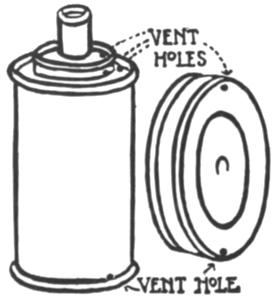
Fig. 98.
Vent Holes.—If a can is used to represent a boiler or is made up into a drum-like structure, such as a wheel, and is not soldered up air tight, it is apt to fill up with the hot lye solution when placed in it. Unless there are two air holes or vents provided in such a boiler or wheel, the lye or water will not all run out when it is removed from the bath, but it will ooze out from time to time perhaps after the toy[205] has been painted for some time. The lye thus liberated will ruin all paint with which it comes in contact.
At least two vent holes should be punched or bored in all drum-like structures employed about the toys, one hole at the top to admit air and another hole at the bottom to allow the water or lye solution to escape. These vent holes are particularly necessary in wheels that are made from cans, see Fig. 98.
The tin toys should be painted with a good grade of enamel paint. Enamel paints have varnish mixed with them and dry hard and glossy and form a very durable and attractive finish for the toys.
There are several popular brands of these enamel paints on the market and almost any of them will give good results if properly applied.
Several colors should be purchased to start with, black, white, cherry red, chrome yellow, prussian or royal blue. With this assortment of colors, it is possible to get a variety of shades by mixing. A can of vermilion and a can of khaki-colored enamel paint, as well as small cans of gold and silver and bronze paint, will prove very handy additions to the above collection of colors. The vermilion, gold and silver paints are used to paint certain details of the toys that need to be emphasized.
Be sure to keep all the cans of paint tightly covered when not in use, so that the paint will not dry up and become thick and gummy from contact with the air.
Several paint brushes should be purchased at the paint dealers, the largest brush should be of soft[207] hair about ½ inch wide, and the smallest brush a tiny pointed one for detail and line work. Always keep these brushes covered with turpentine after using them or wash them out immediately after by scrubbing them on a cake of soap with plenty of warm water.
Cut several small cans down to tray size and use them for mixing the paint.
Always stir up a can of paint before using it. Use a small stick for stirring and keep at it until the paint is thoroughly mixed. Enamel paints may be thinned with turpentine and a bottle of this should be kept on hand.
Do not use your paint too thick. It should be of such a consistency as to drip slowly from the brush before the brush is wiped against the side of the can to remove the surplus paint upon commencing the work.
Be sure to mix up enough paint to cover the entire surface to be painted if using mixed colors, as it is very difficult to mix a second batch of the same shade of color.
Think how you are going to apply your paint before starting. Try to plan your painting so that you will not have to work over a painted surface a second time until that surface is thoroughly dry. The paint should be applied smoothly with a brush. Just enough paint should be held in the[208] brush so that it flows onto the tin without streaks of the tin showing through the paint.
Generally speaking, you should start at the top of a piece of work and paint down. Each fresh brush stroke should overlap the one above it and mop up any surplus paint of the former brush strokes.
Paint the intricate parts first and then the plain surfaces. For instance, when painting the aeroplane weathervane, use a small brush and paint the struts first, then paint around the bases and tops of the struts on the surface of the planes. Change the small brush for a larger one and flow more paint over the surface of the planes, gathering up the paint around the ends of the struts as you paint along.
When painting a large model, such as an army truck, and not being quite sure of the quantity of paint needed, mix up enough paint to paint all the parts of the model that show the most and leave such parts as the bottom of the frame and the inside of the body until last. If you have to mix up more paint for these last parts it will not matter if it is not exactly the same shade.
If you have not had very much experience in mixing and combining colors, it is generally better to use the different tints just as they come from the cans, without trying to mix them.
Do not use too many colors on one toy, but try to get a pleasing effect with two or three colors that look well together. For instance, a truck may be[209] painted an olive green or khaki color over its entire surface, excepting the front of the radiator which should be painted with silver paint.
When the first coat of paint is thoroughly dry, lines of black may be painted about the body and various edges emphasized with black. The hubs of the wheels, the lamps, the rim of the steering wheel, and the filler cap on the radiator may all be painted black with good effect. The part of the wheels which is supposed to represent the tires should be painted a dark gray. (Gray may be made by mixing black and white together.)
Study the large trucks seen about the streets for inspiration. These large trucks are nearly always very simply and attractively painted.
Real locomotives are painted black at present, but a small toy locomotive looks much better if the wheels are painted red (vermilion). A red band may be painted about the top of the smokestack and the tin strips framing the cab windows should be painted red, as may the number of the engine, etc.
The whistle should be painted with gold paint and also the inside of the headlight, and broad lines may be painted about the boiler with gold to represent the straps seen about locomotive boilers.
Paint the tires of the engine wheels with silver paint. The driving rods may be painted either black or silver.
A toy locomotive thus painted will prove far[210] more attractive to a child than if it is painted a plain black like a real locomotive.
Generally speaking, the toys should be painted one dominating color of an attractive tint and relieved or brightened with lines and certain details painted with a bright or contrasting color.
Always allow one coat of paint to dry thoroughly before painting on it again.
Tin toys may be baked in an oven when they are freshly painted. The baking dries the enamel paint very quickly and tends to make the paint dry very hard and smooth. The baking oven of a coal or gas range will do very well for the baking, but be very sure that the oven is not too hot, as a hot oven will cause the solder to melt and the toys to fall apart. It is better to leave the oven door opened slightly when baking the painted toys over a slow fire.
It is not necessary to bake the toys after painting as they may be simply left to dry in the air.
Always paint slowly and carefully. Toys that are attractively painted to match good construction are much more satisfactory than a well-made toy poorly painted.
End of the Project Gutenberg EBook of Making Tin Can Toys, by Edward Thatcher

*** END OF THIS PROJECT GUTENBERG EBOOK MAKING TIN CAN TOYS ***

***** This file should be named 56939-h.htm or 56939-h.zip *****
This and all associated files of various formats will be found in:
        http://www.gutenberg.org/5/6/9/3/56939/

Produced by Chris Curnow and the Online Distributed
Proofreading Team at http://www.pgdp.net (This file was
produced from images generously made available by The
Internet Archive)


Updated editions will replace the previous one--the old editions
will be renamed.

Creating the works from public domain print editions means that no
one owns a United States copyright in these works, so the Foundation
(and you!) can copy and distribute it in the United States without
permission and without paying copyright royalties.  Special rules,
set forth in the General Terms of Use part of this license, apply to
copying and distributing Project Gutenberg-tm electronic works to
protect the PROJECT GUTENBERG-tm concept and trademark.  Project
Gutenberg is a registered trademark, and may not be used if you
charge for the eBooks, unless you receive specific permission.  If you
do not charge anything for copies of this eBook, complying with the
rules is very easy.  You may use this eBook for nearly any purpose
such as creation of derivative works, reports, performances and
research.  They may be modified and printed and given away--you may do
practically ANYTHING with public domain eBooks.  Redistribution is
subject to the trademark license, especially commercial
redistribution.


*** START: FULL LICENSE ***

THE FULL PROJECT GUTENBERG LICENSE
PLEASE READ THIS BEFORE YOU DISTRIBUTE OR USE THIS WORK

To protect the Project Gutenberg-tm mission of promoting the free
distribution of electronic works, by using or distributing this work
(or any other work associated in any way with the phrase "Project
Gutenberg"), you agree to comply with all the terms of the Full Project
Gutenberg-tm License (available with this file or online at
http://gutenberg.org/license).


Section 1.  General Terms of Use and Redistributing Project Gutenberg-tm
electronic works

1.A.  By reading or using any part of this Project Gutenberg-tm
electronic work, you indicate that you have read, understand, agree to
and accept all the terms of this license and intellectual property
(trademark/copyright) agreement.  If you do not agree to abide by all
the terms of this agreement, you must cease using and return or destroy
all copies of Project Gutenberg-tm electronic works in your possession.
If you paid a fee for obtaining a copy of or access to a Project
Gutenberg-tm electronic work and you do not agree to be bound by the
terms of this agreement, you may obtain a refund from the person or
entity to whom you paid the fee as set forth in paragraph 1.E.8.

1.B.  "Project Gutenberg" is a registered trademark.  It may only be
used on or associated in any way with an electronic work by people who
agree to be bound by the terms of this agreement.  There are a few
things that you can do with most Project Gutenberg-tm electronic works
even without complying with the full terms of this agreement.  See
paragraph 1.C below.  There are a lot of things you can do with Project
Gutenberg-tm electronic works if you follow the terms of this agreement
and help preserve free future access to Project Gutenberg-tm electronic
works.  See paragraph 1.E below.

1.C.  The Project Gutenberg Literary Archive Foundation ("the Foundation"
or PGLAF), owns a compilation copyright in the collection of Project
Gutenberg-tm electronic works.  Nearly all the individual works in the
collection are in the public domain in the United States.  If an
individual work is in the public domain in the United States and you are
located in the United States, we do not claim a right to prevent you from
copying, distributing, performing, displaying or creating derivative
works based on the work as long as all references to Project Gutenberg
are removed.  Of course, we hope that you will support the Project
Gutenberg-tm mission of promoting free access to electronic works by
freely sharing Project Gutenberg-tm works in compliance with the terms of
this agreement for keeping the Project Gutenberg-tm name associated with
the work.  You can easily comply with the terms of this agreement by
keeping this work in the same format with its attached full Project
Gutenberg-tm License when you share it without charge with others.

1.D.  The copyright laws of the place where you are located also govern
what you can do with this work.  Copyright laws in most countries are in
a constant state of change.  If you are outside the United States, check
the laws of your country in addition to the terms of this agreement
before downloading, copying, displaying, performing, distributing or
creating derivative works based on this work or any other Project
Gutenberg-tm work.  The Foundation makes no representations concerning
the copyright status of any work in any country outside the United
States.

1.E.  Unless you have removed all references to Project Gutenberg:

1.E.1.  The following sentence, with active links to, or other immediate
access to, the full Project Gutenberg-tm License must appear prominently
whenever any copy of a Project Gutenberg-tm work (any work on which the
phrase "Project Gutenberg" appears, or with which the phrase "Project
Gutenberg" is associated) is accessed, displayed, performed, viewed,
copied or distributed:

This eBook is for the use of anyone anywhere at no cost and with
almost no restrictions whatsoever.  You may copy it, give it away or
re-use it under the terms of the Project Gutenberg License included
with this eBook or online at www.gutenberg.org/license

1.E.2.  If an individual Project Gutenberg-tm electronic work is derived
from the public domain (does not contain a notice indicating that it is
posted with permission of the copyright holder), the work can be copied
and distributed to anyone in the United States without paying any fees
or charges.  If you are redistributing or providing access to a work
with the phrase "Project Gutenberg" associated with or appearing on the
work, you must comply either with the requirements of paragraphs 1.E.1
through 1.E.7 or obtain permission for the use of the work and the
Project Gutenberg-tm trademark as set forth in paragraphs 1.E.8 or
1.E.9.

1.E.3.  If an individual Project Gutenberg-tm electronic work is posted
with the permission of the copyright holder, your use and distribution
must comply with both paragraphs 1.E.1 through 1.E.7 and any additional
terms imposed by the copyright holder.  Additional terms will be linked
to the Project Gutenberg-tm License for all works posted with the
permission of the copyright holder found at the beginning of this work.

1.E.4.  Do not unlink or detach or remove the full Project Gutenberg-tm
License terms from this work, or any files containing a part of this
work or any other work associated with Project Gutenberg-tm.

1.E.5.  Do not copy, display, perform, distribute or redistribute this
electronic work, or any part of this electronic work, without
prominently displaying the sentence set forth in paragraph 1.E.1 with
active links or immediate access to the full terms of the Project
Gutenberg-tm License.

1.E.6.  You may convert to and distribute this work in any binary,
compressed, marked up, nonproprietary or proprietary form, including any
word processing or hypertext form.  However, if you provide access to or
distribute copies of a Project Gutenberg-tm work in a format other than
"Plain Vanilla ASCII" or other format used in the official version
posted on the official Project Gutenberg-tm web site (www.gutenberg.org),
you must, at no additional cost, fee or expense to the user, provide a
copy, a means of exporting a copy, or a means of obtaining a copy upon
request, of the work in its original "Plain Vanilla ASCII" or other
form.  Any alternate format must include the full Project Gutenberg-tm
License as specified in paragraph 1.E.1.

1.E.7.  Do not charge a fee for access to, viewing, displaying,
performing, copying or distributing any Project Gutenberg-tm works
unless you comply with paragraph 1.E.8 or 1.E.9.

1.E.8.  You may charge a reasonable fee for copies of or providing
access to or distributing Project Gutenberg-tm electronic works provided
that

- You pay a royalty fee of 20% of the gross profits you derive from
     the use of Project Gutenberg-tm works calculated using the method
     you already use to calculate your applicable taxes.  The fee is
     owed to the owner of the Project Gutenberg-tm trademark, but he
     has agreed to donate royalties under this paragraph to the
     Project Gutenberg Literary Archive Foundation.  Royalty payments
     must be paid within 60 days following each date on which you
     prepare (or are legally required to prepare) your periodic tax
     returns.  Royalty payments should be clearly marked as such and
     sent to the Project Gutenberg Literary Archive Foundation at the
     address specified in Section 4, "Information about donations to
     the Project Gutenberg Literary Archive Foundation."

- You provide a full refund of any money paid by a user who notifies
     you in writing (or by e-mail) within 30 days of receipt that s/he
     does not agree to the terms of the full Project Gutenberg-tm
     License.  You must require such a user to return or
     destroy all copies of the works possessed in a physical medium
     and discontinue all use of and all access to other copies of
     Project Gutenberg-tm works.

- You provide, in accordance with paragraph 1.F.3, a full refund of any
     money paid for a work or a replacement copy, if a defect in the
     electronic work is discovered and reported to you within 90 days
     of receipt of the work.

- You comply with all other terms of this agreement for free
     distribution of Project Gutenberg-tm works.

1.E.9.  If you wish to charge a fee or distribute a Project Gutenberg-tm
electronic work or group of works on different terms than are set
forth in this agreement, you must obtain permission in writing from
both the Project Gutenberg Literary Archive Foundation and Michael
Hart, the owner of the Project Gutenberg-tm trademark.  Contact the
Foundation as set forth in Section 3 below.

1.F.

1.F.1.  Project Gutenberg volunteers and employees expend considerable
effort to identify, do copyright research on, transcribe and proofread
public domain works in creating the Project Gutenberg-tm
collection.  Despite these efforts, Project Gutenberg-tm electronic
works, and the medium on which they may be stored, may contain
"Defects," such as, but not limited to, incomplete, inaccurate or
corrupt data, transcription errors, a copyright or other intellectual
property infringement, a defective or damaged disk or other medium, a
computer virus, or computer codes that damage or cannot be read by
your equipment.

1.F.2.  LIMITED WARRANTY, DISCLAIMER OF DAMAGES - Except for the "Right
of Replacement or Refund" described in paragraph 1.F.3, the Project
Gutenberg Literary Archive Foundation, the owner of the Project
Gutenberg-tm trademark, and any other party distributing a Project
Gutenberg-tm electronic work under this agreement, disclaim all
liability to you for damages, costs and expenses, including legal
fees.  YOU AGREE THAT YOU HAVE NO REMEDIES FOR NEGLIGENCE, STRICT
LIABILITY, BREACH OF WARRANTY OR BREACH OF CONTRACT EXCEPT THOSE
PROVIDED IN PARAGRAPH 1.F.3.  YOU AGREE THAT THE FOUNDATION, THE
TRADEMARK OWNER, AND ANY DISTRIBUTOR UNDER THIS AGREEMENT WILL NOT BE
LIABLE TO YOU FOR ACTUAL, DIRECT, INDIRECT, CONSEQUENTIAL, PUNITIVE OR
INCIDENTAL DAMAGES EVEN IF YOU GIVE NOTICE OF THE POSSIBILITY OF SUCH
DAMAGE.

1.F.3.  LIMITED RIGHT OF REPLACEMENT OR REFUND - If you discover a
defect in this electronic work within 90 days of receiving it, you can
receive a refund of the money (if any) you paid for it by sending a
written explanation to the person you received the work from.  If you
received the work on a physical medium, you must return the medium with
your written explanation.  The person or entity that provided you with
the defective work may elect to provide a replacement copy in lieu of a
refund.  If you received the work electronically, the person or entity
providing it to you may choose to give you a second opportunity to
receive the work electronically in lieu of a refund.  If the second copy
is also defective, you may demand a refund in writing without further
opportunities to fix the problem.

1.F.4.  Except for the limited right of replacement or refund set forth
in paragraph 1.F.3, this work is provided to you 'AS-IS' WITH NO OTHER
WARRANTIES OF ANY KIND, EXPRESS OR IMPLIED, INCLUDING BUT NOT LIMITED TO
WARRANTIES OF MERCHANTABILITY OR FITNESS FOR ANY PURPOSE.

1.F.5.  Some states do not allow disclaimers of certain implied
warranties or the exclusion or limitation of certain types of damages.
If any disclaimer or limitation set forth in this agreement violates the
law of the state applicable to this agreement, the agreement shall be
interpreted to make the maximum disclaimer or limitation permitted by
the applicable state law.  The invalidity or unenforceability of any
provision of this agreement shall not void the remaining provisions.

1.F.6.  INDEMNITY - You agree to indemnify and hold the Foundation, the
trademark owner, any agent or employee of the Foundation, anyone
providing copies of Project Gutenberg-tm electronic works in accordance
with this agreement, and any volunteers associated with the production,
promotion and distribution of Project Gutenberg-tm electronic works,
harmless from all liability, costs and expenses, including legal fees,
that arise directly or indirectly from any of the following which you do
or cause to occur: (a) distribution of this or any Project Gutenberg-tm
work, (b) alteration, modification, or additions or deletions to any
Project Gutenberg-tm work, and (c) any Defect you cause.


Section  2.  Information about the Mission of Project Gutenberg-tm

Project Gutenberg-tm is synonymous with the free distribution of
electronic works in formats readable by the widest variety of computers
including obsolete, old, middle-aged and new computers.  It exists
because of the efforts of hundreds of volunteers and donations from
people in all walks of life.

Volunteers and financial support to provide volunteers with the
assistance they need, are critical to reaching Project Gutenberg-tm's
goals and ensuring that the Project Gutenberg-tm collection will
remain freely available for generations to come.  In 2001, the Project
Gutenberg Literary Archive Foundation was created to provide a secure
and permanent future for Project Gutenberg-tm and future generations.
To learn more about the Project Gutenberg Literary Archive Foundation
and how your efforts and donations can help, see Sections 3 and 4
and the Foundation web page at http://www.pglaf.org.


Section 3.  Information about the Project Gutenberg Literary Archive
Foundation

The Project Gutenberg Literary Archive Foundation is a non profit
501(c)(3) educational corporation organized under the laws of the
state of Mississippi and granted tax exempt status by the Internal
Revenue Service.  The Foundation's EIN or federal tax identification
number is 64-6221541.  Its 501(c)(3) letter is posted at
http://pglaf.org/fundraising.  Contributions to the Project Gutenberg
Literary Archive Foundation are tax deductible to the full extent
permitted by U.S. federal laws and your state's laws.

The Foundation's principal office is located at 4557 Melan Dr. S.
Fairbanks, AK, 99712., but its volunteers and employees are scattered
throughout numerous locations.  Its business office is located at
809 North 1500 West, Salt Lake City, UT 84116, (801) 596-1887, email
business@pglaf.org.  Email contact links and up to date contact
information can be found at the Foundation's web site and official
page at http://pglaf.org

For additional contact information:
     Dr. Gregory B. Newby
     Chief Executive and Director
     gbnewby@pglaf.org


Section 4.  Information about Donations to the Project Gutenberg
Literary Archive Foundation

Project Gutenberg-tm depends upon and cannot survive without wide
spread public support and donations to carry out its mission of
increasing the number of public domain and licensed works that can be
freely distributed in machine readable form accessible by the widest
array of equipment including outdated equipment.  Many small donations
($1 to $5,000) are particularly important to maintaining tax exempt
status with the IRS.

The Foundation is committed to complying with the laws regulating
charities and charitable donations in all 50 states of the United
States.  Compliance requirements are not uniform and it takes a
considerable effort, much paperwork and many fees to meet and keep up
with these requirements.  We do not solicit donations in locations
where we have not received written confirmation of compliance.  To
SEND DONATIONS or determine the status of compliance for any
particular state visit http://pglaf.org

While we cannot and do not solicit contributions from states where we
have not met the solicitation requirements, we know of no prohibition
against accepting unsolicited donations from donors in such states who
approach us with offers to donate.

International donations are gratefully accepted, but we cannot make
any statements concerning tax treatment of donations received from
outside the United States.  U.S. laws alone swamp our small staff.

Please check the Project Gutenberg Web pages for current donation
methods and addresses.  Donations are accepted in a number of other
ways including checks, online payments and credit card donations.
To donate, please visit: http://pglaf.org/donate


Section 5.  General Information About Project Gutenberg-tm electronic
works.

Professor Michael S. Hart is the originator of the Project Gutenberg-tm
concept of a library of electronic works that could be freely shared
with anyone.  For thirty years, he produced and distributed Project
Gutenberg-tm eBooks with only a loose network of volunteer support.


Project Gutenberg-tm eBooks are often created from several printed
editions, all of which are confirmed as Public Domain in the U.S.
unless a copyright notice is included.  Thus, we do not necessarily
keep eBooks in compliance with any particular paper edition.


Most people start at our Web site which has the main PG search facility:

     http://www.gutenberg.org

This Web site includes information about Project Gutenberg-tm,
including how to make donations to the Project Gutenberg Literary
Archive Foundation, how to help produce our new eBooks, and how to
subscribe to our email newsletter to hear about new eBooks.